Holds all the parts and joins them, like a LEGO baseplate.
Breadboard
Our building board
Loading part…
sequencing multiple outputs with timing
Cycle red, yellow, and green LEDs like a mini traffic signal.
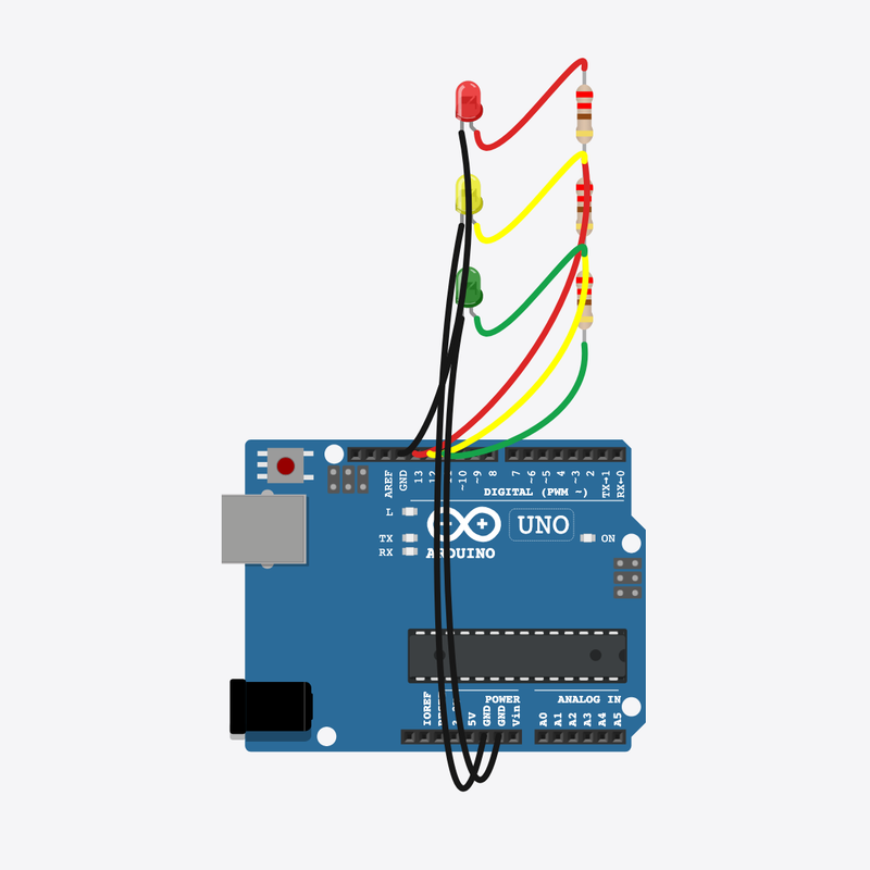
Pin connections
| Part 1 | Part 2 | |
|---|---|---|
Red resistor pin 1 | → | Breadboard 6t b |
Red resistor pin 2 | → | Breadboard 10t b |
Red LED anode (+) | → | Breadboard 4t b |
Red LED cathode (-) | → | Breadboard 3t b |
Yellow resistor pin 1 | → | Breadboard 15t b |
Yellow resistor pin 2 | → | Breadboard 19t b |
Yellow LED anode (+) | → | Breadboard 13t b |
Yellow LED cathode (-) | → | Breadboard 12t b |
Green resistor pin 1 | → | Breadboard 24t b |
Green resistor pin 2 | → | Breadboard 28t b |
Green LED anode (+) | → | Breadboard 22t b |
Green LED cathode (-) | → | Breadboard 21t b |
Arduino pin 13 | → | Breadboard 10t e |
Breadboard 6t e | → | Breadboard 4t e |
Breadboard 3t e | → | Arduino GND |
Arduino pin 12 | → | Breadboard 19t e |
Breadboard 15t e | → | Breadboard 13t e |
Breadboard 12t e | → | Arduino GND |
Arduino pin 11 | → | Breadboard 28t e |
Breadboard 24t e | → | Breadboard 22t e |
Breadboard 21t e | → | Arduino GND |
Let's make a traffic light!
Three lights take turns — red, yellow, green — just like the ones on the road.
You see traffic lights every day at busy roads and crossings!
The problem
One light is fun, but a real traffic light needs three colors that take turns in order.
Think of it like
It's like a teacher calling kids one at a time — only one stands up at a time, and they go in order.
Holds all the parts and joins them, like a LEGO baseplate.
Breadboard
Our building board
It thinks and tells each light when it is their turn.
Arduino
The brain
Glows red to say 'stop and wait'.
Red LED
The stop light
Glows yellow to say 'get ready'.
Yellow LED
The get-ready light
Glows green to say 'go!'.
Green LED
The go light
Keeps the red light safe from too much power.
Red resistor
The protector
Keeps the yellow light safe from too much power.
Yellow resistor
The protector
Keeps the green light safe from too much power.
Green resistor
The protector
Red light
First turn all the lights off, then turn on only red. It glows for 2 seconds.
allOff();
digitalWrite(PIN_RED, HIGH);
delay(2000);
Yellow light
Red turns off and yellow comes on for a quick moment to say 'get ready'.
allOff();
digitalWrite(PIN_YELLOW, HIGH);
delay(800);
Green light
Yellow turns off and green glows for 2 seconds. Then loop() jumps back to red!
allOff();
digitalWrite(PIN_GREEN, HIGH);
delay(2000);
Then loop back to step 1
Follow these steps in order. Match the wires to the colors shown.
Place Breadboard
Place the Breadboard (bb1) on the breadboard.
Breadboard placed — build like the real world!
Place Arduino
Place the Arduino (uno) on the breadboard.
Arduino placed — ready to build!
Place Red LED
Place the Red LED (ledRed) on the breadboard.
Red light plugged in — the stop light!
Place Red resistor
Place the Red resistor (rRed) on the breadboard.
Red resistor in — it keeps the red light safe!
Place Yellow LED
Place the Yellow LED (ledYellow) on the breadboard.
Yellow light plugged in — the get-ready light!
Place Yellow resistor
Place the Yellow resistor (rYellow) on the breadboard.
Yellow resistor in — it keeps the yellow light safe!
Place Green LED
Place the Green LED (ledGreen) on the breadboard.
Green light plugged in — the go light!
Place Green resistor
Place the Green resistor (rGreen) on the breadboard.
Green resistor in — it keeps the green light safe!
Connect Arduino pin 13 to Breadboard (bb1) 10t.e
Arduino pin 13 into the red resistor's column 10 — any free hole in that column
Tip: Arduino pin 13 into the red resistor's column 10 — any free hole in that column
Power can now reach the red light!
Connect Breadboard (bb1) 6t.e to Breadboard (bb1) 4t.e
Jumper the red resistor's column 6 to the red LED's anode column 4
Tip: Jumper the red resistor's column 6 to the red LED's anode column 4
Red resistor joined to the red light!
Connect Breadboard (bb1) 3t.e to Arduino GND
Red LED cathode column 3 straight to Arduino GND
Tip: Red LED cathode column 3 straight to Arduino GND
Red light wired!
Connect Arduino pin 12 to Breadboard (bb1) 19t.e
Arduino pin 12 into the yellow resistor's column 19 — any free hole in that column
Tip: Arduino pin 12 into the yellow resistor's column 19 — any free hole in that column
Power can now reach the yellow light!
Connect Breadboard (bb1) 15t.e to Breadboard (bb1) 13t.e
Jumper the yellow resistor's column 15 to the yellow LED's anode column 13
Tip: Jumper the yellow resistor's column 15 to the yellow LED's anode column 13
Yellow resistor joined to the yellow light!
Connect Breadboard (bb1) 12t.e to Arduino GND
Yellow LED cathode column 12 straight to Arduino GND
Tip: Yellow LED cathode column 12 straight to Arduino GND
Yellow light wired!
Connect Arduino pin 11 to Breadboard (bb1) 28t.e
Arduino pin 11 into the green resistor's column 28 — any free hole in that column
Tip: Arduino pin 11 into the green resistor's column 28 — any free hole in that column
Power can now reach the green light!
Connect Breadboard (bb1) 24t.e to Breadboard (bb1) 22t.e
Jumper the green resistor's column 24 to the green LED's anode column 22
Tip: Jumper the green resistor's column 24 to the green LED's anode column 22
Green resistor joined to the green light!
Connect Breadboard (bb1) 21t.e to Arduino GND
Green LED cathode column 21 straight to Arduino GND
Tip: Green LED cathode column 21 straight to Arduino GND
Circuit complete — all three lights wired!
The three light nicknames
const int PIN_RED = 13;
const int PIN_YELLOW = 12;
const int PIN_GREEN = 11;
Each color gets its own pin number with a friendly name like PIN_RED. The names make the code easy to read.
The allOff() helper
void allOff() {
  digitalWrite(PIN_RED, LOW);
  digitalWrite(PIN_YELLOW, LOW);
  digitalWrite(PIN_GREEN, LOW);
}
This little helper turns every light off. We use it before each new color so only one shines at a time.
The traffic order
void loop() {
  allOff();
  digitalWrite(PIN_RED, HIGH);
  delay(2000);
  allOff();
  digitalWrite(PIN_YELLOW, HIGH);
  delay(800);
  allOff();
  digitalWrite(PIN_GREEN, HIGH);
  delay(2000);
}
loop() shows red, then yellow, then green, in order. The delay numbers pick how long each color stays on.
const int PIN_RED = 13;
const int PIN_YELLOW = 12;
const int PIN_GREEN = 11;
void allOff() {
  digitalWrite(PIN_RED, LOW);
  digitalWrite(PIN_YELLOW, LOW);
  digitalWrite(PIN_GREEN, LOW);
}
void setup() {
  pinMode(PIN_RED, OUTPUT);
  pinMode(PIN_YELLOW, OUTPUT);
  pinMode(PIN_GREEN, OUTPUT);
  allOff();
}
void loop() {
  allOff();
  digitalWrite(PIN_RED, HIGH);
  delay(2000);
  allOff();
  digitalWrite(PIN_YELLOW, HIGH);
  delay(800);
  allOff();
  digitalWrite(PIN_GREEN, HIGH);
  delay(2000);
}
Q1. Which part runs again and again?
Q2. Why do we turn the other lights OFF before turning one ON?
Make red stay on longer — change its delay(2000) to delay(3000).
Hint: Find the delay right after digitalWrite(PIN_RED, HIGH).
Make yellow quicker — change delay(800) to delay(400).
Hint: The yellow delay is on the line after PIN_YELLOW turns on.
A line-by-line tour of the sketch — the same steps as in Robot Gurukul Studio.
Program overview
Big idea
Every Arduino program has a top part, a setup() part that runs once, and a loop() part that runs again and again.
In this project
Three lights take turns — red, then yellow, then green — just like a real traffic light.
Tip
Read from the top to the bottom. Tap any word or line if you need help!
const int PIN_RED = 13;
const int PIN_YELLOW = 12;
const int PIN_GREEN = 11;
void allOff() {
  digitalWrite(PIN_RED, LOW);
  digitalWrite(PIN_YELLOW, LOW);
  digitalWrite(PIN_GREEN, LOW);
}
setup()
Big idea
setup() runs one time when the board turns on.
In this project
It gets pins 13, 12, and 11 ready for the red, yellow, and green lights.
Why here
Things we do only once go inside setup().
void setup() {
  pinMode(PIN_RED, OUTPUT);
  pinMode(PIN_YELLOW, OUTPUT);
  pinMode(PIN_GREEN, OUTPUT);
  allOff();
}
loop()
Big idea
loop() runs again and again, forever.
In this project
This is where the lights change from red to yellow to green and back.
Why here
Things that repeat go inside loop().
void loop() {
  allOff();
  digitalWrite(PIN_RED, HIGH);
  delay(2000);
  allOff();
  digitalWrite(PIN_YELLOW, HIGH);
  delay(800);
  allOff();
  digitalWrite(PIN_GREEN, HIGH);
  delay(2000);
}
Try this: Change a delay number inside loop(), then press Run to make a color stay longer.
pinMode
Big idea
pinMode tells a pin if it will listen or push power out.
In this project
It makes pin 13 ready to push power to the red light.
Why here
It goes in setup() because we only set it once.
pinMode(PIN_RED, OUTPUT);
digitalWrite
Big idea
digitalWrite turns a pin ON or OFF.
In this project
ON lights up a color, OFF turns it dark. Here it turns the red light off.
Why here
It goes in loop() so the lights can keep changing.
digitalWrite(PIN_RED, LOW);
delay
Big idea
delay means wait. Nothing else happens while it waits.
In this project
It keeps a color glowing long enough for everyone to see it.
Why here
Right after we turn a light on.
delay(2000);