Holds all the parts and joins them, like a LEGO baseplate.
Breadboard
Our building board
Loading part…
loop index drives a moving pattern
Light one segment at a time on a bar graph using a loop index.
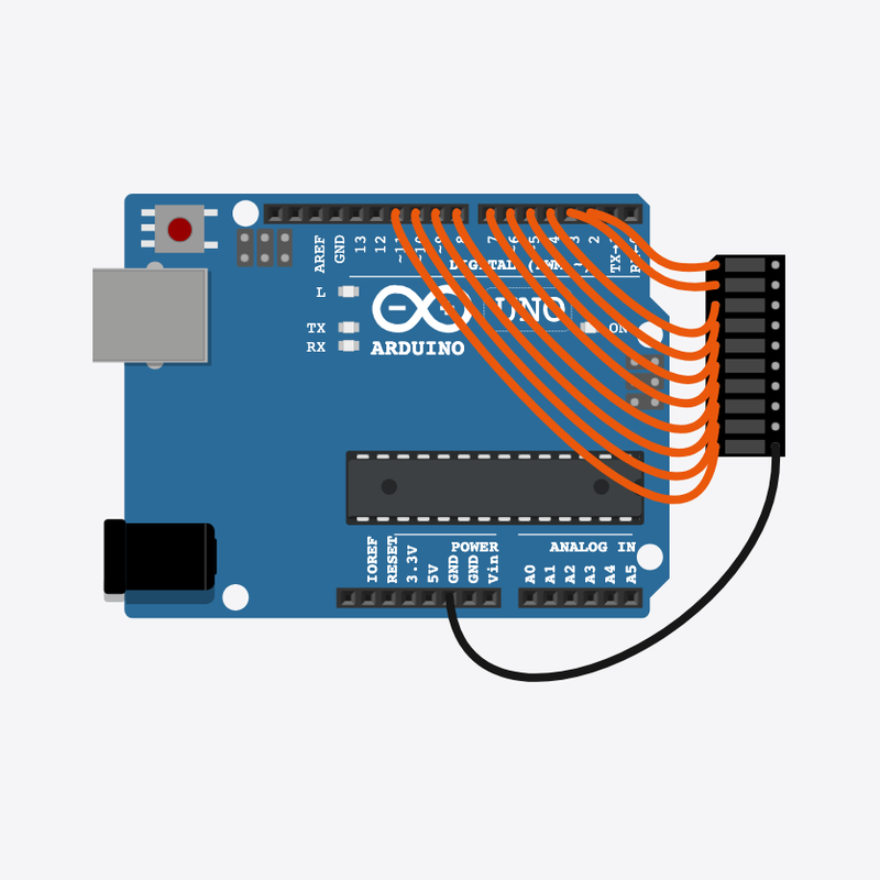
Pin connections
| Part 1 | Part 2 | |
|---|---|---|
Arduino pin 2 | → | LED bar graph A1 |
Arduino pin 3 | → | LED bar graph A2 |
Arduino pin 4 | → | LED bar graph A3 |
Arduino pin 5 | → | LED bar graph A4 |
Arduino pin 6 | → | LED bar graph A5 |
Arduino pin 7 | → | LED bar graph A6 |
Arduino pin 8 | → | LED bar graph A7 |
Arduino pin 9 | → | LED bar graph A8 |
Arduino pin 10 | → | LED bar graph A9 |
Arduino pin 11 | → | LED bar graph A10 |
LED bar graph C10 | → | Arduino GND |
Let's make a running light!
A bright dot zooms along a row of ten lights, like a tiny race car.
You see this on loading bars, volume meters, and fancy car taillights!
The problem
One blinking light is fun, but a moving dot of light is even cooler.
Think of it like
It's like a spotlight at a show — it shines on one kid, then slides to the next.
Holds all the parts and joins them, like a LEGO baseplate.
Breadboard
Our building board
It thinks and tells each light when to glow.
Arduino
The brain
Ten little lights in a line that you can switch on one by one.
LED bar graph
The row of lights
Turn them all off
First we turn every light off, so only one light will glow at a time.
digitalWrite(FIRST_PIN + j, LOW);
Light up one
The number i picks which light glows. That glowing light is our racing dot!
digitalWrite(FIRST_PIN + i, HIGH);
Wait, then move on
A short wait lets us see the dot. Then i goes up by one and the dot jumps to the next light.
delay(100);
Then loop back to step 1
Follow these steps in order. Match the wires to the colors shown.
Place Breadboard
Place the Breadboard (bb1) on the breadboard.
Breadboard placed — build like the real world!
Place Arduino
Place the Arduino (uno) on the breadboard.
Arduino placed — ready to build!
Place LED bar graph
Place the LED bar graph (bar1) on the breadboard.
Row of ten lights placed — now let's wire them up!
Connect Arduino pin 2 to LED bar graph (bar1) A1
Arduino pin 2 to segment 1's anode (A1)
Tip: Arduino pin 2 to segment 1's anode (A1)
Light 1 wired!
Connect Arduino pin 3 to LED bar graph (bar1) A2
Arduino pin 3 to segment 2's anode (A2)
Tip: Arduino pin 3 to segment 2's anode (A2)
Light 2 wired!
Connect Arduino pin 4 to LED bar graph (bar1) A3
Arduino pin 4 to segment 3's anode (A3)
Tip: Arduino pin 4 to segment 3's anode (A3)
Light 3 wired!
Connect Arduino pin 5 to LED bar graph (bar1) A4
Arduino pin 5 to segment 4's anode (A4)
Tip: Arduino pin 5 to segment 4's anode (A4)
Light 4 wired!
Connect Arduino pin 6 to LED bar graph (bar1) A5
Arduino pin 6 to segment 5's anode (A5)
Tip: Arduino pin 6 to segment 5's anode (A5)
Light 5 wired!
Connect Arduino pin 7 to LED bar graph (bar1) A6
Arduino pin 7 to segment 6's anode (A6)
Tip: Arduino pin 7 to segment 6's anode (A6)
Light 6 wired!
Connect Arduino pin 8 to LED bar graph (bar1) A7
Arduino pin 8 to segment 7's anode (A7)
Tip: Arduino pin 8 to segment 7's anode (A7)
Light 7 wired!
Connect Arduino pin 9 to LED bar graph (bar1) A8
Arduino pin 9 to segment 8's anode (A8)
Tip: Arduino pin 9 to segment 8's anode (A8)
Light 8 wired!
Connect Arduino pin 10 to LED bar graph (bar1) A9
Arduino pin 10 to segment 9's anode (A9)
Tip: Arduino pin 10 to segment 9's anode (A9)
Light 9 wired!
Connect Arduino pin 11 to LED bar graph (bar1) A10
Arduino pin 11 to segment 10's anode (A10)
Tip: Arduino pin 11 to segment 10's anode (A10)
All ten lights are wired!
Connect LED bar graph (bar1) C10 to Arduino GND
One wire from the bar graph's common cathode side to Arduino GND — all segments share this ground inside the part
Tip: One wire from the bar graph's common cathode side to Arduino GND — all segments share this ground inside the part
Circuit complete — the dot can run!
How many lights and where
const int FIRST_PIN = 2;
const int NUM_LEDS = 10;
FIRST_PIN is the first light (pin 2) and NUM_LEDS is how many lights there are (10).
Get all the lights ready
void setup() {
  for (int i = 0; i < NUM_LEDS; i++) {
    pinMode(FIRST_PIN + i, OUTPUT);
  }
}
This loop gets every light pin ready, one after another, so they can all glow.
The chasing dot
void loop() {
  for (int i = 0; i < NUM_LEDS; i++) {
    for (int j = 0; j < NUM_LEDS; j++) {
      digitalWrite(FIRST_PIN + j, LOW);
    }
    digitalWrite(FIRST_PIN + i, HIGH);
    delay(100);
  }
}
First all the lights turn off, then one turns on. Doing this over and over makes the dot race along the row.
const int FIRST_PIN = 2;
const int NUM_LEDS = 10;
void setup() {
  for (int i = 0; i < NUM_LEDS; i++) {
    pinMode(FIRST_PIN + i, OUTPUT);
  }
}
void loop() {
  for (int i = 0; i < NUM_LEDS; i++) {
    for (int j = 0; j < NUM_LEDS; j++) {
      digitalWrite(FIRST_PIN + j, LOW);
    }
    digitalWrite(FIRST_PIN + i, HIGH);
    delay(100);
  }
}
Q1. Which part runs again and again?
Q2. What does the number i pick in this program?
Make the dot race faster — change delay(100) to delay(50).
Hint: There is only one delay() inside loop().
Add a little note (comment) on the line that lights one light up.
Hint: Type // and your words at the end of the line with + i.
A line-by-line tour of the sketch — the same steps as in Robot Gurukul Studio.
Program overview
Big idea
Every Arduino program has a top part, a setup() part that runs once, and a loop() part that runs again and again.
In this project
One light at a time glows and the bright dot runs along a bar of ten lights.
Tip
Read from the top to the bottom. Tap any word or line if you need help!
const int FIRST_PIN = 2;
const int NUM_LEDS = 10;
setup()
Big idea
setup() runs one time when the board turns on.
In this project
It gets all ten light pins (starting at pin 2) ready.
Why here
Things we do only once go inside setup().
void setup() {
  for (int i = 0; i < NUM_LEDS; i++) {
    pinMode(FIRST_PIN + i, OUTPUT);
  }
}
loop()
Big idea
loop() runs again and again, forever.
In this project
This is where the glowing dot moves from one light to the next.
Why here
Things that repeat go inside loop().
void loop() {
  for (int i = 0; i < NUM_LEDS; i++) {
    for (int j = 0; j < NUM_LEDS; j++) {
      digitalWrite(FIRST_PIN + j, LOW);
    }
    digitalWrite(FIRST_PIN + i, HIGH);
    delay(100);
  }
}
Try this: Change the delay number inside loop(), then press Run to make the dot race faster or slower.
pinMode
Big idea
pinMode tells a pin if it will listen or push power out.
In this project
It makes each light pin ready to push power to a light.
Why here
It goes in setup() because we only set it once.
pinMode(FIRST_PIN + i, OUTPUT);
digitalWrite
Big idea
digitalWrite turns a pin ON or OFF.
In this project
ON lights up one little light, OFF turns it dark.
Why here
It goes in loop() so the lights can keep changing.
digitalWrite(FIRST_PIN + j, LOW);
delay
Big idea
delay means wait. Nothing else happens while it waits.
In this project
A short wait lets you see the dot before it jumps to the next light.
Why here
Right after we light up a light.
delay(100);