Print or save as PDF

Use your browser's Print dialog (Cmd/Ctrl + P) and choose "Save as PDF".

← Back to book

Welcome to Robot Gurukul!

Your Arduino Adventure — Stages 1 to 3

Introduction

What is this book?

This book helps you learn Arduino step by step through 30 fun projects. Each chapter matches a mission in Robot Gurukul Studio — the same lessons you see in the desktop app, written so you can read, build, and understand even when you are away from the computer.

Safety first

  • Always use a resistor with LEDs — it protects the LED and the Arduino pin.
  • Connect and disconnect wires only when the Arduino is unplugged from USB power.
  • Ask a teacher or adult if you are unsure about any connection.
  • Never connect motors or high-power devices directly to Arduino pins without the right driver circuit.
  • Keep food and drinks away from your breadboard and components.

Stage 1: Output Control

setup(), loop(), digitalWrite(), delay()

Stage 1 is where every Arduino journey begins. You will learn how a program is organized — setup() runs once, loop() runs forever — and how to turn outputs on and off with digitalWrite() and delay().

Mission 01 · Stage 1

Blink LED

setup() and loop() program structure

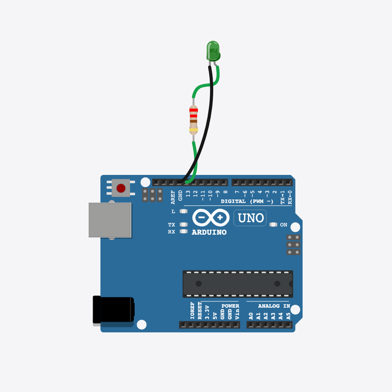
Blink an external LED on a half breadboard through a current-limiting resistor connected to pin 13.
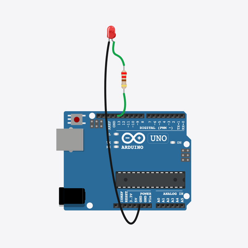
Blink LED circuit diagram

Pin connections

Part 1Part 2

Resistor

pin 1

Breadboard

6t b

Resistor

pin 2

Breadboard

10t b

LED

anode (+)

Breadboard

4t b

LED

cathode (-)

Breadboard

3t b

Arduino

pin 13

Breadboard

10t e

Breadboard

6t e

Breadboard

4t e

Breadboard

3t e

Arduino

GND

See it

Let's make a light blink!

Your very first program turns a tiny light on and off, over and over.

Blinking lights are everywhere — on TVs, toys, and even rockets!

The story

The problem

Before we build cool robots, we need to learn how an Arduino program is put together.

Think of it like

setup() is like getting dressed in the morning — you do it once. loop() is like brushing your teeth every day — you do it again and again.

Meet the parts

Holds all the parts and joins them, like a LEGO baseplate.

Breadboard

Our building board

Loading part…

It thinks and tells the light when to turn on and off.

Arduino

The brain

Loading part…

A tiny light that glows when it gets power.

LED

The light

Loading part…

Slows the power down so the light does not get hurt.

Resistor

The protector

Loading part…

How it works

1

setup() runs once

When the board turns on, setup() gets pin 13 ready. Then it never runs again.

void setup() {
  pinMode(LED_PIN, OUTPUT);
}
2

Turn the light ON

Pin 13 turns ON and the light glows.

digitalWrite(LED_PIN, HIGH);
3

Wait a little

The light stays on for half a second.

delay(500);
4

Turn it OFF and repeat

The light turns off, waits again, then loop() jumps back and does it all over — forever!

digitalWrite(LED_PIN, LOW);
delay(500);

Then loop back to step 2

Build the circuit

Follow these steps in order. Match the wires to the colors shown.

  1. 1

    Place Breadboard

    Place the Breadboard (bb1) on the breadboard.

    Breadboard placed — build like the real world!

    Loading part…
  2. 2

    Place Arduino

    Place the Arduino (uno) on the breadboard.

    Arduino placed — ready to build!

    Loading part…
  3. 3

    Place Resistor

    Place the Resistor (r1) on the breadboard.

    Resistor plugged into the breadboard across columns 6 and 10!

    Loading part…
  4. 4

    Place LED

    Place the LED (led1) on the breadboard.

    LED plugged in — anode in column 4, cathode in column 3!

    Loading part…
  5. 5

    Connect Arduino pin 13 to Breadboard (bb1) 10t.e

    Arduino pin 13 into the resistor's column 10 — use any free hole in that column

    Tip: Arduino pin 13 into the resistor's column 10 — use any free hole in that column

    Signal reaches the resistor through the breadboard!

  6. 6

    Connect Breadboard (bb1) 6t.e to Breadboard (bb1) 4t.e

    Jumper the resistor's column 6 to the LED's anode column 4 — any free hole in each column

    Tip: Jumper the resistor's column 6 to the LED's anode column 4 — any free hole in each column

    Resistor linked to the LED through the breadboard!

  7. 7

    Connect Breadboard (bb1) 3t.e to Arduino GND

    LED cathode column 3 straight to Arduino GND — any free hole in column 3

    Tip: LED cathode column 3 straight to Arduino GND — any free hole in column 3

    Circuit complete!

Try it

  • Press the green Run button — the light should start blinking!
  • Remember: setup() runs once, loop() runs forever.

Peek at code

The light's nickname

const int LED_PIN = 13;

LED_PIN is a nickname for pin 13. Using the nickname makes the code easy to read.

setup() — runs once

void setup() {
  pinMode(LED_PIN, OUTPUT);
}

setup() runs one time when the board turns on. pinMode gets pin 13 ready to power the light.

loop() — blink forever

void loop() {
  digitalWrite(LED_PIN, HIGH);
  delay(500);
  digitalWrite(LED_PIN, LOW);
  delay(500);
}

loop() turns the light on, waits, turns it off, waits — then starts over all by itself!

Show full sketch (blink-led.ino)
const int LED_PIN = 13;
void setup() {
  pinMode(LED_PIN, OUTPUT);
}
void loop() {
  digitalWrite(LED_PIN, HIGH);
  delay(500);
  digitalWrite(LED_PIN, LOW);
  delay(500);
}

Quick quiz

Q1. What does delay(500) do?

  • A. Waits half a second
  • B. Makes the light brighter
  • C. Turns on pin 500
Why: Yes! 500 means half a second between blinks.

Q2. Which part runs only one time when the board turns on?

  • A. setup()
  • B. loop()
  • C. delay()
Why: Right! setup() runs once at the very start.

Code lab — try on your own

  1. Make the light blink faster by making both delay numbers smaller.

    Hint: Try 200 or 300 instead of 500.

  2. Add a little note (comment) on the line that turns the light ON.

    Hint: Type // and your words at the end of that line.

  3. Add a note (comment) on line 1 that tells what LED_PIN is.

    Hint: Like: // my light is on pin 13

Code walkthrough

A line-by-line tour of the sketch — the same steps as in Robot Gurukul Studio.

Program overview

Big idea

Every Arduino program has a top part, a setup() part that runs once, and a loop() part that runs again and again.

In this project

We make a little light blink on and off forever.

Tip

Read from the top to the bottom. Tap any word or line if you need help!

const int LED_PIN = 13;

setup()

Big idea

setup() runs one time when the board turns on.

In this project

It gets pin 13 ready for our light.

Why here

Things we do only once go inside setup().

void setup() {
  pinMode(LED_PIN, OUTPUT);
}

loop()

Big idea

loop() runs again and again, forever.

In this project

This is where the light blinks on and off.

Why here

Things that repeat go inside loop().

void loop() {
  digitalWrite(LED_PIN, HIGH);
  delay(500);
  digitalWrite(LED_PIN, LOW);
  delay(500);
}

Try this: Change a number inside loop(), then press Run to see what happens.

pinMode

Big idea

pinMode tells a pin if it will listen or push power out.

In this project

It makes pin 13 ready to push power to the light.

Why here

It goes in setup() because we only set it once.

  pinMode(LED_PIN, OUTPUT);

digitalWrite

Big idea

digitalWrite turns a pin ON or OFF.

In this project

ON lights up the LED, OFF turns it dark.

Why here

It goes in loop() so the light can keep changing.

  digitalWrite(LED_PIN, HIGH);

delay

Big idea

delay means wait. Nothing else happens while it waits.

In this project

It keeps the light on (or off) long enough for us to see.

Why here

Right after we turn the light on or off.

  delay(500);
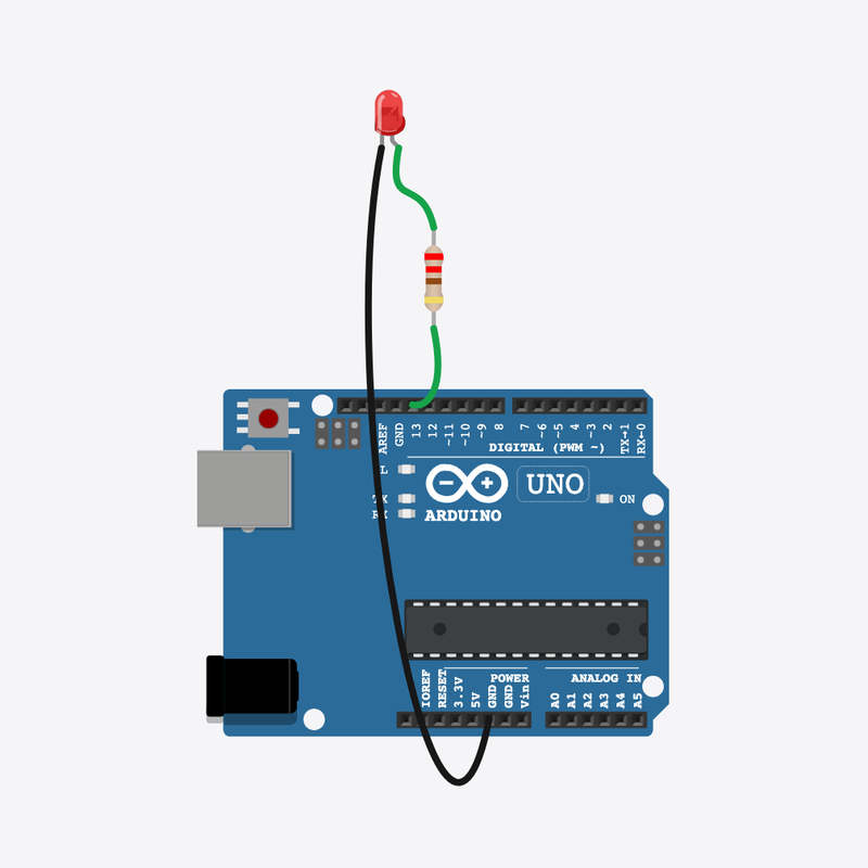
Mission 02 · Stage 1

Fast & Slow Blink

changing delay() values

Alternate fast and slow blink speeds by changing delay() values.

Fast & Slow Blink circuit diagram

Pin connections

Part 1Part 2

Resistor

pin 1

Breadboard

6t b

Resistor

pin 2

Breadboard

10t b

LED

anode (+)

Breadboard

4t b

LED

cathode (-)

Breadboard

3t b

Arduino

pin 13

Breadboard

10t e

Breadboard

6t e

Breadboard

4t e

Breadboard

3t e

Arduino

GND

See it

Let's blink at two speeds!

One little light blinks fast like a heartbeat, then slow like a sleepy yawn.

Fast and slow blinks are everywhere — quick on a game controller, slow on a phone charging.

The story

The problem

One blink speed is a little boring. Let's learn how to make a light blink fast AND slow.

Think of it like

It's like clapping — fast-fast, then slow-slow. The clap is the same, only the waiting changes.

Meet the parts

Holds all the parts and joins them, like a LEGO baseplate.

Breadboard

Our building board

Loading part…

It thinks and tells the light when to blink fast or slow.

Arduino

The brain

Loading part…

Slows the power down so the light does not get hurt.

Resistor

The protector

Loading part…

A tiny light that glows when it gets power.

LED

The light

Loading part…

How it works

1

Blink fast — ON

The light turns on, then waits only a tiny bit (150) — a quick flash.

digitalWrite(LED_PIN, HIGH);
delay(FAST_MS);
2

Blink fast — OFF

The light turns off for the same short wait. That makes the second fast blink.

digitalWrite(LED_PIN, LOW);
delay(FAST_MS);
3

Blink slow — ON

Now the light stays on much longer (800). You can really see this slow blink.

digitalWrite(LED_PIN, HIGH);
delay(SLOW_MS);
4

Blink slow — OFF

After the long wait, loop() jumps back to the fast blinks and does it all again!

digitalWrite(LED_PIN, LOW);
delay(SLOW_MS);

Then loop back to step 1

Build the circuit

Follow these steps in order. Match the wires to the colors shown.

  1. 1

    Place Breadboard

    Place the Breadboard (bb1) on the breadboard.

    Breadboard placed — build like the real world!

    Loading part…
  2. 2

    Place Arduino

    Place the Arduino (uno) on the breadboard.

    Arduino placed — ready to build!

    Loading part…
  3. 3

    Place Resistor

    Place the Resistor (r1) on the breadboard.

    Resistor in — it keeps the light safe!

    Loading part…
  4. 4

    Place LED

    Place the LED (led1) on the breadboard.

    Light plugged in — let's make it blink!

    Loading part…
  5. 5

    Connect Arduino pin 13 to Breadboard (bb1) 10t.e

    Arduino pin 13 into the resistor's column 10 — use any free hole in that column

    Tip: Arduino pin 13 into the resistor's column 10 — use any free hole in that column

    Power can now reach the resistor!

  6. 6

    Connect Breadboard (bb1) 6t.e to Breadboard (bb1) 4t.e

    Jumper the resistor's column 6 to the LED's anode column 4 — any free hole in each column

    Tip: Jumper the resistor's column 6 to the LED's anode column 4 — any free hole in each column

    Resistor joined to the light!

  7. 7

    Connect Breadboard (bb1) 3t.e to Arduino GND

    LED cathode column 3 straight to Arduino GND — any free hole in column 3

    Tip: LED cathode column 3 straight to Arduino GND — any free hole in column 3

    Circuit complete!

Try it

  • Press the green Run button — watch two quick blinks, then two slow ones.
  • Say the rhythm out loud: fast-fast, slow-slow, again and again!

Peek at code

The two speed nicknames

const int LED_PIN = 13;
const int FAST_MS = 150;
const int SLOW_MS = 800;

FAST_MS is the short wait (150) and SLOW_MS is the long wait (800). Change these numbers to change the speeds.

setup() — runs once

void setup() {
  pinMode(LED_PIN, OUTPUT);
}

setup() runs one time when the board turns on. pinMode gets pin 13 ready to power the light.

loop() — fast then slow

void loop() {
  digitalWrite(LED_PIN, HIGH);
  delay(FAST_MS);
  digitalWrite(LED_PIN, LOW);
  delay(FAST_MS);
  digitalWrite(LED_PIN, HIGH);
  delay(SLOW_MS);
  digitalWrite(LED_PIN, LOW);
  delay(SLOW_MS);
}

loop() does two fast blinks, then two slow blinks. The delay numbers — not digitalWrite — pick the speed.

Show full sketch (fast-slow-blink.ino)
const int LED_PIN = 13;
const int FAST_MS = 150;
const int SLOW_MS = 800;
void setup() {
  pinMode(LED_PIN, OUTPUT);
}
void loop() {
  digitalWrite(LED_PIN, HIGH);
  delay(FAST_MS);
  digitalWrite(LED_PIN, LOW);
  delay(FAST_MS);
  digitalWrite(LED_PIN, HIGH);
  delay(SLOW_MS);
  digitalWrite(LED_PIN, LOW);
  delay(SLOW_MS);
}

Quick quiz

Q1. Which part runs again and again?

  • A. loop()
  • B. setup()
  • C. pinMode only
Why: Yes! loop() runs again and again, forever.

Q2. What does a bigger number inside delay() do?

  • A. Waits longer
  • B. Makes the light brighter
  • C. Runs setup() again
Why: Yes! A bigger number means a longer wait, so the blink is slower.

Code lab — try on your own

  1. Make the fast blinks even quicker by making FAST_MS smaller.

    Hint: Try 80 or 100 instead of 150 on the FAST_MS line.

  2. Make the slow blinks even longer by making SLOW_MS bigger.

    Hint: Try 1200 or 1500 instead of 800 on the SLOW_MS line.

Code walkthrough

A line-by-line tour of the sketch — the same steps as in Robot Gurukul Studio.

Program overview

Big idea

Every Arduino program has a top part, a setup() part that runs once, and a loop() part that runs again and again.

In this project

The light blinks two quick blinks, then two slow blinks, forever.

Tip

Read from the top to the bottom. Tap any word or line if you need help!

const int LED_PIN = 13;
const int FAST_MS = 150;
const int SLOW_MS = 800;

setup()

Big idea

setup() runs one time when the board turns on.

In this project

It gets pin 13 ready for our light.

Why here

Things we do only once go inside setup().

void setup() {
  pinMode(LED_PIN, OUTPUT);
}

loop()

Big idea

loop() runs again and again, forever.

In this project

This is where the light blinks fast, then slow.

Why here

Things that repeat go inside loop().

void loop() {
  digitalWrite(LED_PIN, HIGH);
  delay(FAST_MS);
  digitalWrite(LED_PIN, LOW);
  delay(FAST_MS);
  digitalWrite(LED_PIN, HIGH);
  delay(SLOW_MS);
  digitalWrite(LED_PIN, LOW);
  delay(SLOW_MS);
}

Try this: Change a delay number inside loop(), then press Run to see the blink speed change.

pinMode

Big idea

pinMode tells a pin if it will listen or push power out.

In this project

It makes pin 13 ready to push power to the light.

Why here

It goes in setup() because we only set it once.

  pinMode(LED_PIN, OUTPUT);

digitalWrite

Big idea

digitalWrite turns a pin ON or OFF.

In this project

ON lights up the LED, OFF turns it dark.

Why here

It goes in loop() so the light can keep changing.

  digitalWrite(LED_PIN, HIGH);

delay

Big idea

delay means wait. Nothing else happens while it waits.

In this project

A short wait makes fast blinks, a long wait makes slow blinks.

Why here

Right after we turn the light on or off.

  delay(FAST_MS);
Mission 03 · Stage 1

Traffic Light

sequencing multiple outputs with timing

Cycle red, yellow, and green LEDs like a mini traffic signal.

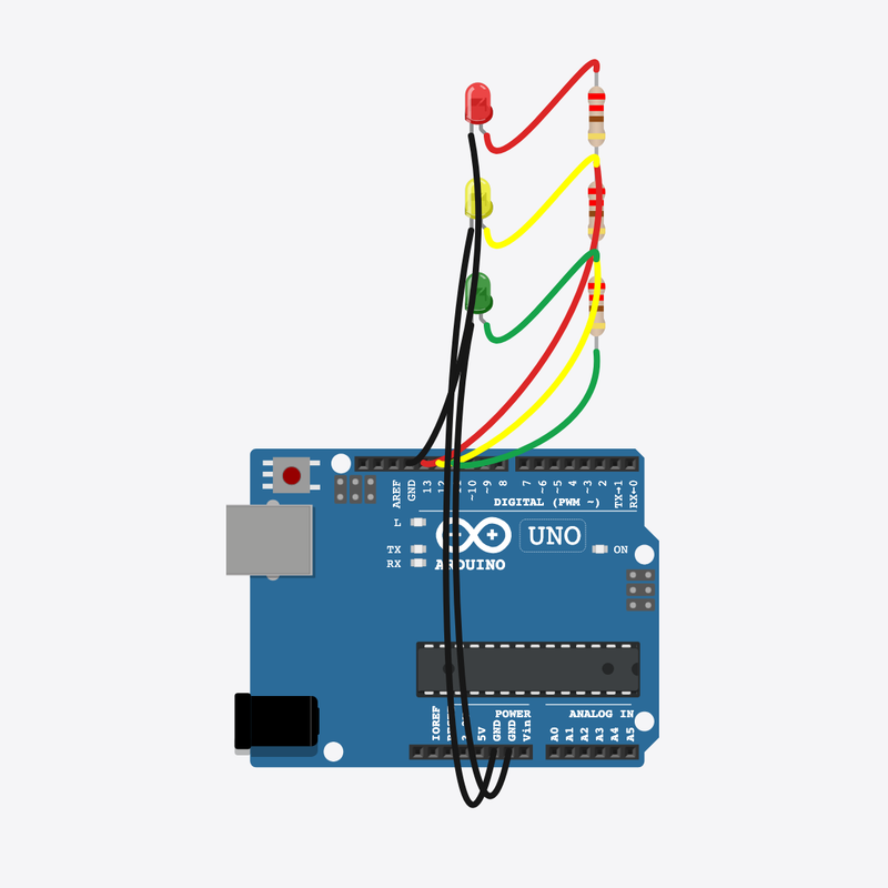
Traffic Light circuit diagram

Pin connections

Part 1Part 2

Red resistor

pin 1

Breadboard

6t b

Red resistor

pin 2

Breadboard

10t b

Red LED

anode (+)

Breadboard

4t b

Red LED

cathode (-)

Breadboard

3t b

Yellow resistor

pin 1

Breadboard

15t b

Yellow resistor

pin 2

Breadboard

19t b

Yellow LED

anode (+)

Breadboard

13t b

Yellow LED

cathode (-)

Breadboard

12t b

Green resistor

pin 1

Breadboard

24t b

Green resistor

pin 2

Breadboard

28t b

Green LED

anode (+)

Breadboard

22t b

Green LED

cathode (-)

Breadboard

21t b

Arduino

pin 13

Breadboard

10t e

Breadboard

6t e

Breadboard

4t e

Breadboard

3t e

Arduino

GND

Arduino

pin 12

Breadboard

19t e

Breadboard

15t e

Breadboard

13t e

Breadboard

12t e

Arduino

GND

Arduino

pin 11

Breadboard

28t e

Breadboard

24t e

Breadboard

22t e

Breadboard

21t e

Arduino

GND

See it

Let's make a traffic light!

Three lights take turns — red, yellow, green — just like the ones on the road.

You see traffic lights every day at busy roads and crossings!

The story

The problem

One light is fun, but a real traffic light needs three colors that take turns in order.

Think of it like

It's like a teacher calling kids one at a time — only one stands up at a time, and they go in order.

Meet the parts

Holds all the parts and joins them, like a LEGO baseplate.

Breadboard

Our building board

Loading part…

It thinks and tells each light when it is their turn.

Arduino

The brain

Loading part…

Glows red to say 'stop and wait'.

Red LED

The stop light

Loading part…

Glows yellow to say 'get ready'.

Yellow LED

The get-ready light

Loading part…

Glows green to say 'go!'.

Green LED

The go light

Loading part…

Keeps the red light safe from too much power.

Red resistor

The protector

Loading part…

Keeps the yellow light safe from too much power.

Yellow resistor

The protector

Loading part…

Keeps the green light safe from too much power.

Green resistor

The protector

Loading part…

How it works

1

Red light

First turn all the lights off, then turn on only red. It glows for 2 seconds.

allOff();
digitalWrite(PIN_RED, HIGH);
delay(2000);
2

Yellow light

Red turns off and yellow comes on for a quick moment to say 'get ready'.

allOff();
digitalWrite(PIN_YELLOW, HIGH);
delay(800);
3

Green light

Yellow turns off and green glows for 2 seconds. Then loop() jumps back to red!

allOff();
digitalWrite(PIN_GREEN, HIGH);
delay(2000);

Then loop back to step 1

Build the circuit

Follow these steps in order. Match the wires to the colors shown.

  1. 1

    Place Breadboard

    Place the Breadboard (bb1) on the breadboard.

    Breadboard placed — build like the real world!

    Loading part…
  2. 2

    Place Arduino

    Place the Arduino (uno) on the breadboard.

    Arduino placed — ready to build!

    Loading part…
  3. 3

    Place Red LED

    Place the Red LED (ledRed) on the breadboard.

    Red light plugged in — the stop light!

    Loading part…
  4. 4

    Place Red resistor

    Place the Red resistor (rRed) on the breadboard.

    Red resistor in — it keeps the red light safe!

    Loading part…
  5. 5

    Place Yellow LED

    Place the Yellow LED (ledYellow) on the breadboard.

    Yellow light plugged in — the get-ready light!

    Loading part…
  6. 6

    Place Yellow resistor

    Place the Yellow resistor (rYellow) on the breadboard.

    Yellow resistor in — it keeps the yellow light safe!

    Loading part…
  7. 7

    Place Green LED

    Place the Green LED (ledGreen) on the breadboard.

    Green light plugged in — the go light!

    Loading part…
  8. 8

    Place Green resistor

    Place the Green resistor (rGreen) on the breadboard.

    Green resistor in — it keeps the green light safe!

    Loading part…
  9. 9

    Connect Arduino pin 13 to Breadboard (bb1) 10t.e

    Arduino pin 13 into the red resistor's column 10 — any free hole in that column

    Tip: Arduino pin 13 into the red resistor's column 10 — any free hole in that column

    Power can now reach the red light!

  10. 10

    Connect Breadboard (bb1) 6t.e to Breadboard (bb1) 4t.e

    Jumper the red resistor's column 6 to the red LED's anode column 4

    Tip: Jumper the red resistor's column 6 to the red LED's anode column 4

    Red resistor joined to the red light!

  11. 11

    Connect Breadboard (bb1) 3t.e to Arduino GND

    Red LED cathode column 3 straight to Arduino GND

    Tip: Red LED cathode column 3 straight to Arduino GND

    Red light wired!

  12. 12

    Connect Arduino pin 12 to Breadboard (bb1) 19t.e

    Arduino pin 12 into the yellow resistor's column 19 — any free hole in that column

    Tip: Arduino pin 12 into the yellow resistor's column 19 — any free hole in that column

    Power can now reach the yellow light!

  13. 13

    Connect Breadboard (bb1) 15t.e to Breadboard (bb1) 13t.e

    Jumper the yellow resistor's column 15 to the yellow LED's anode column 13

    Tip: Jumper the yellow resistor's column 15 to the yellow LED's anode column 13

    Yellow resistor joined to the yellow light!

  14. 14

    Connect Breadboard (bb1) 12t.e to Arduino GND

    Yellow LED cathode column 12 straight to Arduino GND

    Tip: Yellow LED cathode column 12 straight to Arduino GND

    Yellow light wired!

  15. 15

    Connect Arduino pin 11 to Breadboard (bb1) 28t.e

    Arduino pin 11 into the green resistor's column 28 — any free hole in that column

    Tip: Arduino pin 11 into the green resistor's column 28 — any free hole in that column

    Power can now reach the green light!

  16. 16

    Connect Breadboard (bb1) 24t.e to Breadboard (bb1) 22t.e

    Jumper the green resistor's column 24 to the green LED's anode column 22

    Tip: Jumper the green resistor's column 24 to the green LED's anode column 22

    Green resistor joined to the green light!

  17. 17

    Connect Breadboard (bb1) 21t.e to Arduino GND

    Green LED cathode column 21 straight to Arduino GND

    Tip: Green LED cathode column 21 straight to Arduino GND

    Circuit complete — all three lights wired!

Try it

  • Press the green Run button — only one light should glow at a time.
  • Watch the order: red, then yellow, then green, then start over!

Peek at code

The three light nicknames

const int PIN_RED = 13;
const int PIN_YELLOW = 12;
const int PIN_GREEN = 11;

Each color gets its own pin number with a friendly name like PIN_RED. The names make the code easy to read.

The allOff() helper

void allOff() {
  digitalWrite(PIN_RED, LOW);
  digitalWrite(PIN_YELLOW, LOW);
  digitalWrite(PIN_GREEN, LOW);
}

This little helper turns every light off. We use it before each new color so only one shines at a time.

The traffic order

void loop() {
  allOff();
  digitalWrite(PIN_RED, HIGH);
  delay(2000);
  allOff();
  digitalWrite(PIN_YELLOW, HIGH);
  delay(800);
  allOff();
  digitalWrite(PIN_GREEN, HIGH);
  delay(2000);
}

loop() shows red, then yellow, then green, in order. The delay numbers pick how long each color stays on.

Show full sketch (traffic-light.ino)
const int PIN_RED = 13;
const int PIN_YELLOW = 12;
const int PIN_GREEN = 11;
void allOff() {
  digitalWrite(PIN_RED, LOW);
  digitalWrite(PIN_YELLOW, LOW);
  digitalWrite(PIN_GREEN, LOW);
}
void setup() {
  pinMode(PIN_RED, OUTPUT);
  pinMode(PIN_YELLOW, OUTPUT);
  pinMode(PIN_GREEN, OUTPUT);
  allOff();
}
void loop() {
  allOff();
  digitalWrite(PIN_RED, HIGH);
  delay(2000);
  allOff();
  digitalWrite(PIN_YELLOW, HIGH);
  delay(800);
  allOff();
  digitalWrite(PIN_GREEN, HIGH);
  delay(2000);
}

Quick quiz

Q1. Which part runs again and again?

  • A. loop()
  • B. setup()
  • C. pinMode only
Why: Yes! loop() runs again and again, forever.

Q2. Why do we turn the other lights OFF before turning one ON?

  • A. So only one color shows at a time
  • B. To save pin numbers
  • C. Because delay() needs it
Why: Yes! A real traffic light shows just one color at a time.

Code lab — try on your own

  1. Make red stay on longer — change its delay(2000) to delay(3000).

    Hint: Find the delay right after digitalWrite(PIN_RED, HIGH).

  2. Make yellow quicker — change delay(800) to delay(400).

    Hint: The yellow delay is on the line after PIN_YELLOW turns on.

Code walkthrough

A line-by-line tour of the sketch — the same steps as in Robot Gurukul Studio.

Program overview

Big idea

Every Arduino program has a top part, a setup() part that runs once, and a loop() part that runs again and again.

In this project

Three lights take turns — red, then yellow, then green — just like a real traffic light.

Tip

Read from the top to the bottom. Tap any word or line if you need help!

const int PIN_RED = 13;
const int PIN_YELLOW = 12;
const int PIN_GREEN = 11;
void allOff() {
  digitalWrite(PIN_RED, LOW);
  digitalWrite(PIN_YELLOW, LOW);
  digitalWrite(PIN_GREEN, LOW);
}

setup()

Big idea

setup() runs one time when the board turns on.

In this project

It gets pins 13, 12, and 11 ready for the red, yellow, and green lights.

Why here

Things we do only once go inside setup().

void setup() {
  pinMode(PIN_RED, OUTPUT);
  pinMode(PIN_YELLOW, OUTPUT);
  pinMode(PIN_GREEN, OUTPUT);
  allOff();
}

loop()

Big idea

loop() runs again and again, forever.

In this project

This is where the lights change from red to yellow to green and back.

Why here

Things that repeat go inside loop().

void loop() {
  allOff();
  digitalWrite(PIN_RED, HIGH);
  delay(2000);
  allOff();
  digitalWrite(PIN_YELLOW, HIGH);
  delay(800);
  allOff();
  digitalWrite(PIN_GREEN, HIGH);
  delay(2000);
}

Try this: Change a delay number inside loop(), then press Run to make a color stay longer.

pinMode

Big idea

pinMode tells a pin if it will listen or push power out.

In this project

It makes pin 13 ready to push power to the red light.

Why here

It goes in setup() because we only set it once.

  pinMode(PIN_RED, OUTPUT);

digitalWrite

Big idea

digitalWrite turns a pin ON or OFF.

In this project

ON lights up a color, OFF turns it dark. Here it turns the red light off.

Why here

It goes in loop() so the lights can keep changing.

  digitalWrite(PIN_RED, LOW);

delay

Big idea

delay means wait. Nothing else happens while it waits.

In this project

It keeps a color glowing long enough for everyone to see it.

Why here

Right after we turn a light on.

  delay(2000);
Mission 04 · Stage 1

LED Chaser

loop index drives a moving pattern

Light one segment at a time on a bar graph using a loop index.

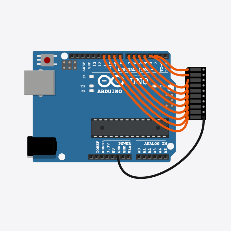
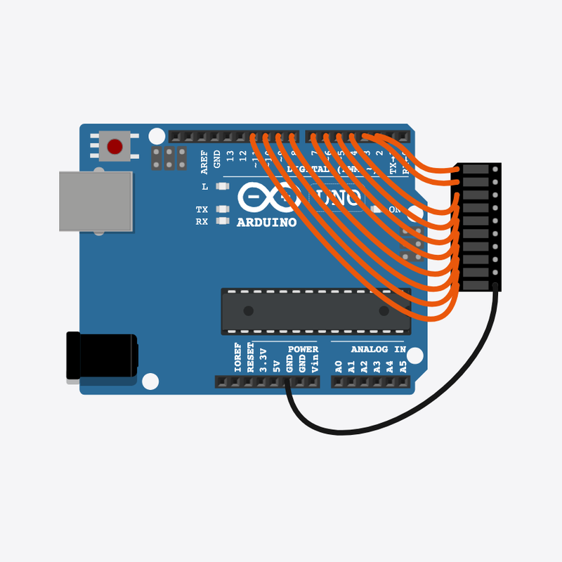
LED Chaser circuit diagram

Pin connections

Part 1Part 2

Arduino

pin 2

LED bar graph

A1

Arduino

pin 3

LED bar graph

A2

Arduino

pin 4

LED bar graph

A3

Arduino

pin 5

LED bar graph

A4

Arduino

pin 6

LED bar graph

A5

Arduino

pin 7

LED bar graph

A6

Arduino

pin 8

LED bar graph

A7

Arduino

pin 9

LED bar graph

A8

Arduino

pin 10

LED bar graph

A9

Arduino

pin 11

LED bar graph

A10

LED bar graph

C10

Arduino

GND

See it

Let's make a running light!

A bright dot zooms along a row of ten lights, like a tiny race car.

You see this on loading bars, volume meters, and fancy car taillights!

The story

The problem

One blinking light is fun, but a moving dot of light is even cooler.

Think of it like

It's like a spotlight at a show — it shines on one kid, then slides to the next.

Meet the parts

Holds all the parts and joins them, like a LEGO baseplate.

Breadboard

Our building board

Loading part…

It thinks and tells each light when to glow.

Arduino

The brain

Loading part…

Ten little lights in a line that you can switch on one by one.

LED bar graph

The row of lights

Loading part…

How it works

1

Turn them all off

First we turn every light off, so only one light will glow at a time.

digitalWrite(FIRST_PIN + j, LOW);
2

Light up one

The number i picks which light glows. That glowing light is our racing dot!

digitalWrite(FIRST_PIN + i, HIGH);
3

Wait, then move on

A short wait lets us see the dot. Then i goes up by one and the dot jumps to the next light.

delay(100);

Then loop back to step 1

Build the circuit

Follow these steps in order. Match the wires to the colors shown.

  1. 1

    Place Breadboard

    Place the Breadboard (bb1) on the breadboard.

    Breadboard placed — build like the real world!

    Loading part…
  2. 2

    Place Arduino

    Place the Arduino (uno) on the breadboard.

    Arduino placed — ready to build!

    Loading part…
  3. 3

    Place LED bar graph

    Place the LED bar graph (bar1) on the breadboard.

    Row of ten lights placed — now let's wire them up!

    Loading part…
  4. 4

    Connect Arduino pin 2 to LED bar graph (bar1) A1

    Arduino pin 2 to segment 1's anode (A1)

    Tip: Arduino pin 2 to segment 1's anode (A1)

    Light 1 wired!

  5. 5

    Connect Arduino pin 3 to LED bar graph (bar1) A2

    Arduino pin 3 to segment 2's anode (A2)

    Tip: Arduino pin 3 to segment 2's anode (A2)

    Light 2 wired!

  6. 6

    Connect Arduino pin 4 to LED bar graph (bar1) A3

    Arduino pin 4 to segment 3's anode (A3)

    Tip: Arduino pin 4 to segment 3's anode (A3)

    Light 3 wired!

  7. 7

    Connect Arduino pin 5 to LED bar graph (bar1) A4

    Arduino pin 5 to segment 4's anode (A4)

    Tip: Arduino pin 5 to segment 4's anode (A4)

    Light 4 wired!

  8. 8

    Connect Arduino pin 6 to LED bar graph (bar1) A5

    Arduino pin 6 to segment 5's anode (A5)

    Tip: Arduino pin 6 to segment 5's anode (A5)

    Light 5 wired!

  9. 9

    Connect Arduino pin 7 to LED bar graph (bar1) A6

    Arduino pin 7 to segment 6's anode (A6)

    Tip: Arduino pin 7 to segment 6's anode (A6)

    Light 6 wired!

  10. 10

    Connect Arduino pin 8 to LED bar graph (bar1) A7

    Arduino pin 8 to segment 7's anode (A7)

    Tip: Arduino pin 8 to segment 7's anode (A7)

    Light 7 wired!

  11. 11

    Connect Arduino pin 9 to LED bar graph (bar1) A8

    Arduino pin 9 to segment 8's anode (A8)

    Tip: Arduino pin 9 to segment 8's anode (A8)

    Light 8 wired!

  12. 12

    Connect Arduino pin 10 to LED bar graph (bar1) A9

    Arduino pin 10 to segment 9's anode (A9)

    Tip: Arduino pin 10 to segment 9's anode (A9)

    Light 9 wired!

  13. 13

    Connect Arduino pin 11 to LED bar graph (bar1) A10

    Arduino pin 11 to segment 10's anode (A10)

    Tip: Arduino pin 11 to segment 10's anode (A10)

    All ten lights are wired!

  14. 14

    Connect LED bar graph (bar1) C10 to Arduino GND

    One wire from the bar graph's common cathode side to Arduino GND — all segments share this ground inside the part

    Tip: One wire from the bar graph's common cathode side to Arduino GND — all segments share this ground inside the part

    Circuit complete — the dot can run!

Try it

  • Press the green Run button — follow the bright dot from one end to the other.
  • Only one light should glow at a time!

Peek at code

How many lights and where

const int FIRST_PIN = 2;
const int NUM_LEDS = 10;

FIRST_PIN is the first light (pin 2) and NUM_LEDS is how many lights there are (10).

Get all the lights ready

void setup() {
  for (int i = 0; i < NUM_LEDS; i++) {
    pinMode(FIRST_PIN + i, OUTPUT);
  }
}

This loop gets every light pin ready, one after another, so they can all glow.

The chasing dot

void loop() {
  for (int i = 0; i < NUM_LEDS; i++) {
    for (int j = 0; j < NUM_LEDS; j++) {
      digitalWrite(FIRST_PIN + j, LOW);
    }
    digitalWrite(FIRST_PIN + i, HIGH);
    delay(100);
  }
}

First all the lights turn off, then one turns on. Doing this over and over makes the dot race along the row.

Show full sketch (led-chaser.ino)
const int FIRST_PIN = 2;
const int NUM_LEDS = 10;
void setup() {
  for (int i = 0; i < NUM_LEDS; i++) {
    pinMode(FIRST_PIN + i, OUTPUT);
  }
}
void loop() {
  for (int i = 0; i < NUM_LEDS; i++) {
    for (int j = 0; j < NUM_LEDS; j++) {
      digitalWrite(FIRST_PIN + j, LOW);
    }
    digitalWrite(FIRST_PIN + i, HIGH);
    delay(100);
  }
}

Quick quiz

Q1. Which part runs again and again?

  • A. loop()
  • B. setup()
  • C. pinMode only
Why: Yes! loop() runs again and again, forever.

Q2. What does the number i pick in this program?

  • A. Which light is glowing
  • B. How bright the row is
  • C. A random number
Why: Yes! i is the number that picks which light glows right now.

Code lab — try on your own

  1. Make the dot race faster — change delay(100) to delay(50).

    Hint: There is only one delay() inside loop().

  2. Add a little note (comment) on the line that lights one light up.

    Hint: Type // and your words at the end of the line with + i.

Code walkthrough

A line-by-line tour of the sketch — the same steps as in Robot Gurukul Studio.

Program overview

Big idea

Every Arduino program has a top part, a setup() part that runs once, and a loop() part that runs again and again.

In this project

One light at a time glows and the bright dot runs along a bar of ten lights.

Tip

Read from the top to the bottom. Tap any word or line if you need help!

const int FIRST_PIN = 2;
const int NUM_LEDS = 10;

setup()

Big idea

setup() runs one time when the board turns on.

In this project

It gets all ten light pins (starting at pin 2) ready.

Why here

Things we do only once go inside setup().

void setup() {
  for (int i = 0; i < NUM_LEDS; i++) {
    pinMode(FIRST_PIN + i, OUTPUT);
  }
}

loop()

Big idea

loop() runs again and again, forever.

In this project

This is where the glowing dot moves from one light to the next.

Why here

Things that repeat go inside loop().

void loop() {
  for (int i = 0; i < NUM_LEDS; i++) {
    for (int j = 0; j < NUM_LEDS; j++) {
      digitalWrite(FIRST_PIN + j, LOW);
    }
    digitalWrite(FIRST_PIN + i, HIGH);
    delay(100);
  }
}

Try this: Change the delay number inside loop(), then press Run to make the dot race faster or slower.

pinMode

Big idea

pinMode tells a pin if it will listen or push power out.

In this project

It makes each light pin ready to push power to a light.

Why here

It goes in setup() because we only set it once.

    pinMode(FIRST_PIN + i, OUTPUT);

digitalWrite

Big idea

digitalWrite turns a pin ON or OFF.

In this project

ON lights up one little light, OFF turns it dark.

Why here

It goes in loop() so the lights can keep changing.

      digitalWrite(FIRST_PIN + j, LOW);

delay

Big idea

delay means wait. Nothing else happens while it waits.

In this project

A short wait lets you see the dot before it jumps to the next light.

Why here

Right after we light up a light.

    delay(100);
Mission 05 · Stage 1

Multiple LED Patterns

nested loops and pattern tables

Show different bar graph patterns stored in tables and loops.

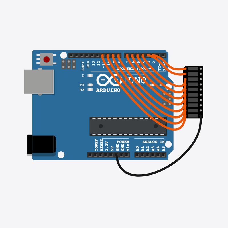
Multiple LED Patterns circuit diagram

Pin connections

Part 1Part 2

Arduino

pin 2

LED bar graph

A1

Arduino

pin 3

LED bar graph

A2

Arduino

pin 4

LED bar graph

A3

Arduino

pin 5

LED bar graph

A4

Arduino

pin 6

LED bar graph

A5

Arduino

pin 7

LED bar graph

A6

Arduino

pin 8

LED bar graph

A7

Arduino

pin 9

LED bar graph

A8

Arduino

pin 10

LED bar graph

A9

Arduino

pin 11

LED bar graph

A10

LED bar graph

C10

Arduino

GND

See it

Let's make light shapes!

A row of lights shows stripes, then pairs, then a glowing block — again and again.

Big screens and scoreboards show saved shapes just like this!

The story

The problem

Typing every single light by hand is a lot of work. Let's save the shapes and reuse them.

Think of it like

It's like a coloring book — the shapes are drawn once, and you fill them in again and again.

Meet the parts

Holds all the parts and joins them, like a LEGO baseplate.

Breadboard

Our building board

Loading part…

It reads the saved shapes and tells the lights what to do.

Arduino

The brain

Loading part…

Ten little lights in a line that make the shapes.

LED bar graph

The row of lights

Loading part…

How it works

1

Show the stripes

patternA is a list of 1s and 0s. A 1 means a light glows and a 0 means it stays dark — together they make stripes.

showPattern(patternA);
delay(400);
2

Show the pairs

patternB is a different list, so the lights make a different shape — two on, two off.

showPattern(patternB);
delay(400);
3

Show the middle block

patternC lights up the middle lights. Then loop() jumps back to the stripes and does it all again!

showPattern(patternC);
delay(400);

Then loop back to step 1

Build the circuit

Follow these steps in order. Match the wires to the colors shown.

  1. 1

    Place Breadboard

    Place the Breadboard (bb1) on the breadboard.

    Breadboard placed — build like the real world!

    Loading part…
  2. 2

    Place Arduino

    Place the Arduino (uno) on the breadboard.

    Arduino placed — ready to build!

    Loading part…
  3. 3

    Place LED bar graph

    Place the LED bar graph (bar1) on the breadboard.

    Row of ten lights placed — now let's wire them up!

    Loading part…
  4. 4

    Connect Arduino pin 2 to LED bar graph (bar1) A1

    Arduino pin 2 to segment 1's anode (A1)

    Tip: Arduino pin 2 to segment 1's anode (A1)

    Light 1 wired!

  5. 5

    Connect Arduino pin 3 to LED bar graph (bar1) A2

    Arduino pin 3 to segment 2's anode (A2)

    Tip: Arduino pin 3 to segment 2's anode (A2)

    Light 2 wired!

  6. 6

    Connect Arduino pin 4 to LED bar graph (bar1) A3

    Arduino pin 4 to segment 3's anode (A3)

    Tip: Arduino pin 4 to segment 3's anode (A3)

    Light 3 wired!

  7. 7

    Connect Arduino pin 5 to LED bar graph (bar1) A4

    Arduino pin 5 to segment 4's anode (A4)

    Tip: Arduino pin 5 to segment 4's anode (A4)

    Light 4 wired!

  8. 8

    Connect Arduino pin 6 to LED bar graph (bar1) A5

    Arduino pin 6 to segment 5's anode (A5)

    Tip: Arduino pin 6 to segment 5's anode (A5)

    Light 5 wired!

  9. 9

    Connect Arduino pin 7 to LED bar graph (bar1) A6

    Arduino pin 7 to segment 6's anode (A6)

    Tip: Arduino pin 7 to segment 6's anode (A6)

    Light 6 wired!

  10. 10

    Connect Arduino pin 8 to LED bar graph (bar1) A7

    Arduino pin 8 to segment 7's anode (A7)

    Tip: Arduino pin 8 to segment 7's anode (A7)

    Light 7 wired!

  11. 11

    Connect Arduino pin 9 to LED bar graph (bar1) A8

    Arduino pin 9 to segment 8's anode (A8)

    Tip: Arduino pin 9 to segment 8's anode (A8)

    Light 8 wired!

  12. 12

    Connect Arduino pin 10 to LED bar graph (bar1) A9

    Arduino pin 10 to segment 9's anode (A9)

    Tip: Arduino pin 10 to segment 9's anode (A9)

    Light 9 wired!

  13. 13

    Connect Arduino pin 11 to LED bar graph (bar1) A10

    Arduino pin 11 to segment 10's anode (A10)

    Tip: Arduino pin 11 to segment 10's anode (A10)

    All ten lights are wired!

  14. 14

    Connect LED bar graph (bar1) C10 to Arduino GND

    One wire from the bar graph's common cathode side to Arduino GND — all segments share this ground inside the part

    Tip: One wire from the bar graph's common cathode side to Arduino GND — all segments share this ground inside the part

    Circuit complete — the shapes can play!

Try it

  • Press the green Run button — try to name each shape before it changes.
  • The shapes come from the saved lists at the top — not magic!

Peek at code

The saved shapes

const byte patternA[] = {1, 0, 1, 0, 1, 0, 1, 0, 1, 0};
const byte patternB[] = {1, 1, 0, 0, 1, 1, 0, 0, 1, 1};
const byte patternC[] = {0, 0, 0, 0, 1, 1, 1, 1, 0, 0};

Each list holds 1s and 0s. A 1 means a light glows and a 0 means it stays dark. A new shape is just a new list!

The showPattern helper

void showPattern(const byte *pat) {
  for (int i = 0; i < NUM_LEDS; i++) {
    digitalWrite(FIRST_PIN + i, pat[i] ? HIGH : LOW);
  }
}

This little helper reads a shape's list and lights each light ON or OFF. We reuse it for every shape.

Play the shapes

void loop() {
  showPattern(patternA);
  delay(400);
  showPattern(patternB);
  delay(400);
  showPattern(patternC);
  delay(400);
}

loop() shows shape A, then B, then C, with a wait between each. That is the whole repeating light show.

Show full sketch (led-patterns.ino)
const int FIRST_PIN = 2;
const int NUM_LEDS = 10;
const byte patternA[] = {1, 0, 1, 0, 1, 0, 1, 0, 1, 0};
const byte patternB[] = {1, 1, 0, 0, 1, 1, 0, 0, 1, 1};
const byte patternC[] = {0, 0, 0, 0, 1, 1, 1, 1, 0, 0};
void showPattern(const byte *pat) {
  for (int i = 0; i < NUM_LEDS; i++) {
    digitalWrite(FIRST_PIN + i, pat[i] ? HIGH : LOW);
  }
}
void setup() {
  for (int i = 0; i < NUM_LEDS; i++) {
    pinMode(FIRST_PIN + i, OUTPUT);
  }
}
void loop() {
  showPattern(patternA);
  delay(400);
  showPattern(patternB);
  delay(400);
  showPattern(patternC);
  delay(400);
}

Quick quiz

Q1. Which part runs again and again?

  • A. loop()
  • B. setup()
  • C. pinMode only
Why: Yes! loop() runs again and again, forever.

Q2. Why do we save the shapes in lists like patternA?

  • A. So we can reuse a shape with one helper
  • B. To make the Arduino faster
  • C. To replace pinMode()
Why: Yes! A saved list plus a helper saves us from typing every light by hand.

Code lab — try on your own

  1. Speed up the show — change all the delay(400) numbers to delay(200).

    Hint: There are three delay(400) lines inside loop().

  2. Change the first shape — flip a 1 to a 0 (or a 0 to a 1) on line 3.

    Hint: Edit the numbers inside the curly braces of patternA.

Code walkthrough

A line-by-line tour of the sketch — the same steps as in Robot Gurukul Studio.

Program overview

Big idea

Every Arduino program has a top part, a setup() part that runs once, and a loop() part that runs again and again.

In this project

A row of ten lights shows three saved shapes, then starts over.

Tip

Read from the top to the bottom. Tap any word or line if you need help!

const int FIRST_PIN = 2;
const int NUM_LEDS = 10;
const byte patternA[] = {1, 0, 1, 0, 1, 0, 1, 0, 1, 0};
const byte patternB[] = {1, 1, 0, 0, 1, 1, 0, 0, 1, 1};
const byte patternC[] = {0, 0, 0, 0, 1, 1, 1, 1, 0, 0};
void showPattern(const byte *pat) {
  for (int i = 0; i < NUM_LEDS; i++) {
    digitalWrite(FIRST_PIN + i, pat[i] ? HIGH : LOW);
  }
}

setup()

Big idea

setup() runs one time when the board turns on.

In this project

It gets all ten light pins (starting at pin 2) ready.

Why here

Things we do only once go inside setup().

void setup() {
  for (int i = 0; i < NUM_LEDS; i++) {
    pinMode(FIRST_PIN + i, OUTPUT);
  }
}

loop()

Big idea

loop() runs again and again, forever.

In this project

This is where the three light shapes take turns on the bar.

Why here

Things that repeat go inside loop().

void loop() {
  showPattern(patternA);
  delay(400);
  showPattern(patternB);
  delay(400);
  showPattern(patternC);
  delay(400);
}

Try this: Change a delay number inside loop(), then press Run to make each shape hold longer.

pinMode

Big idea

pinMode tells a pin if it will listen or push power out.

In this project

It makes each light pin ready to push power to a light.

Why here

It goes in setup() because we only set it once.

    pinMode(FIRST_PIN + i, OUTPUT);

digitalWrite

Big idea

digitalWrite turns a pin ON or OFF.

In this project

It looks at the shape's list and lights each light ON for a 1 or OFF for a 0.

Why here

It goes in loop() so the shapes can keep changing.

    digitalWrite(FIRST_PIN + i, pat[i] ? HIGH : LOW);

delay

Big idea

delay means wait. Nothing else happens while it waits.

In this project

It holds each shape on screen long enough for you to see it.

Why here

Right after we show a shape.

  delay(400);
Mission 06 · Stage 1

Alternate LEDs

alternating output states

Turn two LEDs on and off in opposite states.

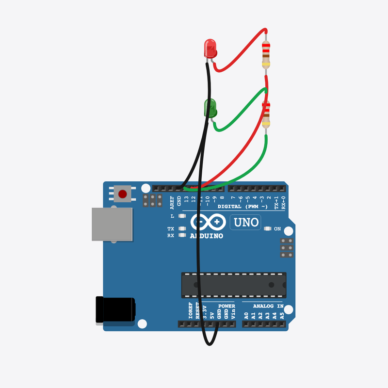
Alternate LEDs circuit diagram

Pin connections

Part 1Part 2

Arduino

pin 12

Red resistor

pin 2

Red resistor

pin 1

Red LED

anode (+)

Red LED

cathode (-)

Arduino

GND

Arduino

pin 13

Green resistor

pin 2

Green resistor

pin 1

Green LED

anode (+)

Green LED

cathode (-)

Arduino

GND

See it

Let's make two lights take turns!

When the red light is on, the green one is off — they swap back and forth like a seesaw.

You see this in car turn signals and railway crossing lights!

The story

The problem

We want two lights that are never on at the same time — they should take turns.

Think of it like

It's like a seesaw — when one side goes up, the other side goes down.

Meet the parts

It thinks and tells the two lights when to swap.

Arduino

The brain

Loading part…

Glows red when it is its turn.

Red LED

The first light

Loading part…

Glows green when it is its turn.

Green LED

The second light

Loading part…

Keeps the red light safe from too much power.

Red resistor

The protector

Loading part…

Keeps the green light safe from too much power.

Green resistor

The protector

Loading part…

How it works

1

First light on

The first light (pin 12) turns on while the second light (pin 13) stays off.

digitalWrite(LED_A, HIGH);
digitalWrite(LED_B, LOW);
2

Wait a little

Both lights hold still for a moment so you can see which one is glowing.

delay(300);
3

Swap to the other

Now they trade places — the first light goes off and the second one glows. Just like a seesaw!

digitalWrite(LED_A, LOW);
digitalWrite(LED_B, HIGH);
4

Wait, then repeat

Another short wait, then loop() jumps back and swaps the lights again!

delay(300);

Then loop back to step 1

Build the circuit

Follow these steps in order. Match the wires to the colors shown.

  1. 1

    Place Arduino

    Place the Arduino (uno) on the breadboard.

    Arduino placed — ready to build!

    Loading part…
  2. 2

    Place Red LED

    Place the Red LED (ledA) on the breadboard.

    Loading part…
  3. 3

    Place Green LED

    Place the Green LED (ledB) on the breadboard.

    Loading part…
  4. 4

    Place Red resistor

    Place the Red resistor (rA) on the breadboard.

    Loading part…
  5. 5

    Place Green resistor

    Place the Green resistor (rB) on the breadboard.

    Loading part…
  6. 6

    Connect Arduino pin 12 to Red resistor (rA) 2

    Connect Arduino pin 12 to Red resistor (rA) 2.

  7. 7

    Connect Red resistor (rA) 1 to Red LED (ledA) anode (+)

    Connect Red resistor (rA) 1 to Red LED (ledA) anode (+).

  8. 8

    Connect Red LED (ledA) cathode (-) to Arduino GND

    Connect Red LED (ledA) cathode (-) to Arduino GND.

  9. 9

    Connect Arduino pin 13 to Green resistor (rB) 2

    Connect Arduino pin 13 to Green resistor (rB) 2.

  10. 10

    Connect Green resistor (rB) 1 to Green LED (ledB) anode (+)

    Connect Green resistor (rB) 1 to Green LED (ledB) anode (+).

  11. 11

    Connect Green LED (ledB) cathode (-) to Arduino GND

    Connect Green LED (ledB) cathode (-) to Arduino GND.

Try it

  • Press the green Run button — red and green should never glow brightly at the same time.
  • Watch them take turns, back and forth, like a blinker!

Peek at code

The two light nicknames

const int LED_A = 12;
const int LED_B = 13;

LED_A is pin 12 and LED_B is pin 13. These are the two lights that take turns.

Get both lights ready

void setup() {
  pinMode(LED_A, OUTPUT);
  pinMode(LED_B, OUTPUT);
}

setup() gets both pins ready so we can turn each light on and off.

The swapping loop

void loop() {
  digitalWrite(LED_A, HIGH);
  digitalWrite(LED_B, LOW);
  delay(300);
  digitalWrite(LED_A, LOW);
  digitalWrite(LED_B, HIGH);
  delay(300);
}

Each half of loop() turns one light on and the other off, with a short wait between swaps.

Show full sketch (alternate-leds.ino)
const int LED_A = 12;
const int LED_B = 13;
void setup() {
  pinMode(LED_A, OUTPUT);
  pinMode(LED_B, OUTPUT);
}
void loop() {
  digitalWrite(LED_A, HIGH);
  digitalWrite(LED_B, LOW);
  delay(300);
  digitalWrite(LED_A, LOW);
  digitalWrite(LED_B, HIGH);
  delay(300);
}

Quick quiz

Q1. Which part runs again and again?

  • A. loop()
  • B. setup()
  • C. pinMode only
Why: Yes! loop() runs again and again, forever.

Q2. When the first light is ON, the second light should be…

  • A. OFF (the opposite)
  • B. ON (the same)
  • C. Unplugged
Why: Yes! Taking turns means when one is on, the other is off.

Code lab — try on your own

  1. Make the lights swap faster — change both delay(300) to delay(150).

    Hint: There are two matching delay lines inside loop().

  2. Add a little note (comment) on the line that turns the first light on.

    Hint: Type // and your words at the end of line 8.

Code walkthrough

A line-by-line tour of the sketch — the same steps as in Robot Gurukul Studio.

Program overview

Big idea

Every Arduino program has a top part, a setup() part that runs once, and a loop() part that runs again and again.

In this project

Two lights take turns — one glows while the other is dark, again and again.

Tip

Read from the top to the bottom. Tap any word or line if you need help!

const int LED_A = 12;
const int LED_B = 13;

setup()

Big idea

setup() runs one time when the board turns on.

In this project

It gets pin 12 and pin 13 ready for our two lights.

Why here

Things we do only once go inside setup().

void setup() {
  pinMode(LED_A, OUTPUT);
  pinMode(LED_B, OUTPUT);
}

loop()

Big idea

loop() runs again and again, forever.

In this project

This is where the two lights swap turns over and over.

Why here

Things that repeat go inside loop().

void loop() {
  digitalWrite(LED_A, HIGH);
  digitalWrite(LED_B, LOW);
  delay(300);
  digitalWrite(LED_A, LOW);
  digitalWrite(LED_B, HIGH);
  delay(300);
}

Try this: Change a delay number inside loop(), then press Run to make the lights swap faster.

pinMode

Big idea

pinMode tells a pin if it will listen or push power out.

In this project

It makes pin 12 ready to push power to the first light.

Why here

It goes in setup() because we only set it once.

  pinMode(LED_A, OUTPUT);

digitalWrite

Big idea

digitalWrite turns a pin ON or OFF.

In this project

ON lights up a light, OFF turns it dark. Here it turns the first light on.

Why here

It goes in loop() so the lights can keep changing.

  digitalWrite(LED_A, HIGH);

delay

Big idea

delay means wait. Nothing else happens while it waits.

In this project

It holds the lights still long enough for you to see who is on.

Why here

Right after we set the two lights.

  delay(300);
Mission 07 · Stage 1

RGB LED Basics

three digital outputs for RGB channels

Turn red, green, and blue channels on and off with digitalWrite().

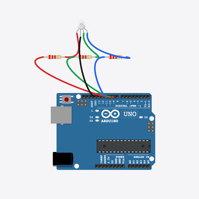
RGB LED Basics circuit diagram

Pin connections

Part 1Part 2

Arduino

pin 9

Red resistor

pin 1

Red resistor

pin 2

RGB LED

red (R)

Arduino

pin 10

Green resistor

pin 1

Green resistor

pin 2

RGB LED

green (G)

Arduino

pin 11

Blue resistor

pin 1

Blue resistor

pin 2

RGB LED

blue (B)

RGB LED

common (COM)

Arduino

GND

See it

Let's make a color-changing light!

One tiny light can glow red, then green, then blue, like magic.

Color lights are in phone screens, TVs, and fun party lamps!

The story

The problem

A normal light only shows one color. This special light hides three colors inside!

Think of it like

It's like having three light switches in one bulb — one for red, one for green, one for blue.

Meet the parts

It thinks and tells the light which color to show.

Arduino

The brain

Loading part…

One little bulb that can glow red, green, or blue.

RGB LED

The color light

Loading part…

Keeps the red color safe from too much power.

Red resistor

The protector

Loading part…

Keeps the green color safe from too much power.

Green resistor

The protector

Loading part…

Keeps the blue color safe from too much power.

Blue resistor

The protector

Loading part…

How it works

1

Glow red

Turn all the colors off first, then turn on only red. The light glows red!

allOff();
digitalWrite(PIN_R, HIGH);
delay(500);
2

Glow green

Red turns off and green comes on. Only one color glows at a time.

allOff();
digitalWrite(PIN_G, HIGH);
delay(500);
3

Glow blue

Green turns off and blue glows. Then loop() jumps back to red and starts again!

allOff();
digitalWrite(PIN_B, HIGH);
delay(500);

Then loop back to step 1

Build the circuit

Follow these steps in order. Match the wires to the colors shown.

  1. 1

    Place Arduino

    Place the Arduino (uno) on the breadboard.

    Arduino placed — ready to build!

    Loading part…
  2. 2

    Place RGB LED

    Place the RGB LED (rgb1) on the breadboard.

    Loading part…
  3. 3

    Place Red resistor

    Place the Red resistor (rr) on the breadboard.

    Loading part…
  4. 4

    Place Green resistor

    Place the Green resistor (rg) on the breadboard.

    Loading part…
  5. 5

    Place Blue resistor

    Place the Blue resistor (rb) on the breadboard.

    Loading part…
  6. 6

    Connect Arduino pin 9 to Red resistor (rr) 1

    Connect Arduino pin 9 to Red resistor (rr) 1.

  7. 7

    Connect Red resistor (rr) 2 to RGB LED (rgb1) R

    Connect Red resistor (rr) 2 to RGB LED (rgb1) R.

  8. 8

    Connect Arduino pin 10 to Green resistor (rg) 1

    Connect Arduino pin 10 to Green resistor (rg) 1.

  9. 9

    Connect Green resistor (rg) 2 to RGB LED (rgb1) G

    Connect Green resistor (rg) 2 to RGB LED (rgb1) G.

  10. 10

    Connect Arduino pin 11 to Blue resistor (rb) 1

    Connect Arduino pin 11 to Blue resistor (rb) 1.

  11. 11

    Connect Blue resistor (rb) 2 to RGB LED (rgb1) B

    Connect Blue resistor (rb) 2 to RGB LED (rgb1) B.

  12. 12

    Connect RGB LED (rgb1) COM to Arduino GND

    Connect RGB LED (rgb1) COM to Arduino GND.

Try it

  • Press the green Run button — the light should change red, then green, then blue.
  • Only one color glows at a time!

Peek at code

The three color nicknames

const int PIN_R = 9;
const int PIN_G = 10;
const int PIN_B = 11;

This light has three colors inside, so it needs three pins — one for red, one for green, one for blue.

The allOff() helper

void allOff() {
  digitalWrite(PIN_R, LOW);
  digitalWrite(PIN_G, LOW);
  digitalWrite(PIN_B, LOW);
}

This little helper turns all three colors off, so each new color starts fresh.

The color cycle

void loop() {
  allOff();
  digitalWrite(PIN_R, HIGH);
  delay(500);
  allOff();
  digitalWrite(PIN_G, HIGH);
  delay(500);
  allOff();
  digitalWrite(PIN_B, HIGH);
  delay(500);
}

loop() shows red, then green, then blue, each with the same short wait. Then it starts over!

Show full sketch (rgb-led-basics.ino)
const int PIN_R = 9;
const int PIN_G = 10;
const int PIN_B = 11;
void allOff() {
  digitalWrite(PIN_R, LOW);
  digitalWrite(PIN_G, LOW);
  digitalWrite(PIN_B, LOW);
}
void setup() {
  pinMode(PIN_R, OUTPUT);
  pinMode(PIN_G, OUTPUT);
  pinMode(PIN_B, OUTPUT);
}
void loop() {
  allOff();
  digitalWrite(PIN_R, HIGH);
  delay(500);
  allOff();
  digitalWrite(PIN_G, HIGH);
  delay(500);
  allOff();
  digitalWrite(PIN_B, HIGH);
  delay(500);
}

Quick quiz

Q1. Which part runs again and again?

  • A. loop()
  • B. setup()
  • C. pinMode only
Why: Yes! loop() runs again and again, forever.

Q2. How many pins does this color light need?

  • A. Three — one for each color
  • B. One pin for everything
  • C. None — it just knows
Why: Yes! Red, green, and blue each get their own pin.

Code lab — try on your own

  1. Show each color quicker — change every delay(500) to delay(250).

    Hint: There are three delay lines inside loop(), one after each color.

  2. Add a little note (comment) on the line that turns red on.

    Hint: It is the line right after the first allOff() inside loop().

Code walkthrough

A line-by-line tour of the sketch — the same steps as in Robot Gurukul Studio.

Program overview

Big idea

Every Arduino program has a top part, a setup() part that runs once, and a loop() part that runs again and again.

In this project

One special light glows red, then green, then blue, forever.

Tip

Read from the top to the bottom. Tap any word or line if you need help!

const int PIN_R = 9;
const int PIN_G = 10;
const int PIN_B = 11;
void allOff() {
  digitalWrite(PIN_R, LOW);
  digitalWrite(PIN_G, LOW);
  digitalWrite(PIN_B, LOW);
}

setup()

Big idea

setup() runs one time when the board turns on.

In this project

It gets pins 9, 10, and 11 ready for the red, green, and blue colors.

Why here

Things we do only once go inside setup().

void setup() {
  pinMode(PIN_R, OUTPUT);
  pinMode(PIN_G, OUTPUT);
  pinMode(PIN_B, OUTPUT);
}

loop()

Big idea

loop() runs again and again, forever.

In this project

This is where the light changes color from red to green to blue.

Why here

Things that repeat go inside loop().

void loop() {
  allOff();
  digitalWrite(PIN_R, HIGH);
  delay(500);
  allOff();
  digitalWrite(PIN_G, HIGH);
  delay(500);
  allOff();
  digitalWrite(PIN_B, HIGH);
  delay(500);
}

Try this: Change a delay number inside loop(), then press Run to make each color last longer.

pinMode

Big idea

pinMode tells a pin if it will listen or push power out.

In this project

It makes pin 9 ready to push power to the red color.

Why here

It goes in setup() because we only set it once.

  pinMode(PIN_R, OUTPUT);

digitalWrite

Big idea

digitalWrite turns a pin ON or OFF.

In this project

ON lights up a color, OFF turns it dark. Here it turns the red color off.

Why here

It goes in loop() so the colors can keep changing.

  digitalWrite(PIN_R, LOW);

delay

Big idea

delay means wait. Nothing else happens while it waits.

In this project

It keeps each color glowing long enough for you to see it.

Why here

Right after we turn a color on.

  delay(500);
Mission 08 · Stage 1

RGB Color Mixer

combining channel values for colors

Mix RGB channels to make yellow, cyan, magenta, and white.

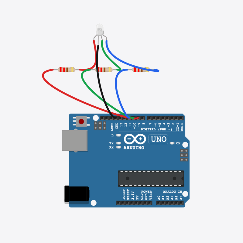
RGB Color Mixer circuit diagram

Pin connections

Part 1Part 2

Arduino

pin 9

Red resistor

pin 1

Red resistor

pin 2

RGB LED

red (R)

Arduino

pin 10

Green resistor

pin 1

Green resistor

pin 2

RGB LED

green (G)

Arduino

pin 11

Blue resistor

pin 1

Blue resistor

pin 2

RGB LED

blue (B)

RGB LED

common (COM)

Arduino

GND

See it

Let's mix our own colors!

Turn on two colors at once and a brand new color appears, like mixing paint!

TVs and phone screens make every color by mixing red, green, and blue!

The story

The problem

One color at a time is fun, but mixing colors lets us make so many more.

Think of it like

It's like mixing paint — red and green together make yellow!

Meet the parts

It thinks and mixes the colors for the light.

Arduino

The brain

Loading part…

One little bulb that holds red, green, and blue together.

RGB LED

The color light

Loading part…

Keeps the red color safe from too much power.

Red resistor

The protector

Loading part…

Keeps the green color safe from too much power.

Green resistor

The protector

Loading part…

Keeps the blue color safe from too much power.

Blue resistor

The protector

Loading part…

How it works

1

Just red

Only the red color is on, so the light glows red.

setChannels(HIGH, LOW, LOW);
2

Red + green = yellow

Turn on red and green together and you get yellow — your first color mix!

setChannels(HIGH, HIGH, LOW);
3

Just green

Now only green is on, so the light glows green.

setChannels(LOW, HIGH, LOW);
4

Green + blue = cyan

Green and blue together make a cool sky-blue color called cyan.

setChannels(LOW, HIGH, HIGH);
5

Just blue

Now only blue is on, so the light glows blue.

setChannels(LOW, LOW, HIGH);
6

Red + blue = magenta

Red and blue together make a pretty pink-purple color called magenta.

setChannels(HIGH, LOW, HIGH);
7

All three = white

All three colors on at once look white! Then loop() jumps back to red and starts again.

setChannels(HIGH, HIGH, HIGH);

Then loop back to step 1

Build the circuit

Follow these steps in order. Match the wires to the colors shown.

  1. 1

    Place Arduino

    Place the Arduino (uno) on the breadboard.

    Arduino placed — ready to build!

    Loading part…
  2. 2

    Place RGB LED

    Place the RGB LED (rgb1) on the breadboard.

    Loading part…
  3. 3

    Place Red resistor

    Place the Red resistor (rr) on the breadboard.

    Loading part…
  4. 4

    Place Green resistor

    Place the Green resistor (rg) on the breadboard.

    Loading part…
  5. 5

    Place Blue resistor

    Place the Blue resistor (rb) on the breadboard.

    Loading part…
  6. 6

    Connect Arduino pin 9 to Red resistor (rr) 1

    Connect Arduino pin 9 to Red resistor (rr) 1.

  7. 7

    Connect Red resistor (rr) 2 to RGB LED (rgb1) R

    Connect Red resistor (rr) 2 to RGB LED (rgb1) R.

  8. 8

    Connect Arduino pin 10 to Green resistor (rg) 1

    Connect Arduino pin 10 to Green resistor (rg) 1.

  9. 9

    Connect Green resistor (rg) 2 to RGB LED (rgb1) G

    Connect Green resistor (rg) 2 to RGB LED (rgb1) G.

  10. 10

    Connect Arduino pin 11 to Blue resistor (rb) 1

    Connect Arduino pin 11 to Blue resistor (rb) 1.

  11. 11

    Connect Blue resistor (rb) 2 to RGB LED (rgb1) B

    Connect Blue resistor (rb) 2 to RGB LED (rgb1) B.

  12. 12

    Connect RGB LED (rgb1) COM to Arduino GND

    Connect RGB LED (rgb1) COM to Arduino GND.

Try it

  • Press the green Run button — call out each color name as it changes.
  • When two colors are on together, that is a mix — watch for the new color!

Peek at code

The setChannels helper

void setChannels(int r, int g, int b) {
  digitalWrite(PIN_R, r);
  digitalWrite(PIN_G, g);
  digitalWrite(PIN_B, b);
}

This little helper turns all three colors on or off at once. It makes mixing colors easy.

Get the colors ready

void setup() {
  pinMode(PIN_R, OUTPUT);
  pinMode(PIN_G, OUTPUT);
  pinMode(PIN_B, OUTPUT);
}

setup() gets all three color pins ready so we can light any of them.

The color mixing loop

void loop() {
  setChannels(HIGH, LOW, LOW);
  delay(600);
  setChannels(HIGH, HIGH, LOW);
  delay(600);
  setChannels(LOW, HIGH, LOW);
  delay(600);
  setChannels(LOW, HIGH, HIGH);
  delay(600);
  setChannels(LOW, LOW, HIGH);
  delay(600);
  setChannels(HIGH, LOW, HIGH);
  delay(600);
  setChannels(HIGH, HIGH, HIGH);
  delay(600);
}

Each setChannels line is a color recipe. Turning on two or three colors together makes brand new colors.

Show full sketch (rgb-color-mixer.ino)
const int PIN_R = 9;
const int PIN_G = 10;
const int PIN_B = 11;
void setChannels(int r, int g, int b) {
  digitalWrite(PIN_R, r);
  digitalWrite(PIN_G, g);
  digitalWrite(PIN_B, b);
}
void setup() {
  pinMode(PIN_R, OUTPUT);
  pinMode(PIN_G, OUTPUT);
  pinMode(PIN_B, OUTPUT);
}
void loop() {
  setChannels(HIGH, LOW, LOW);
  delay(600);
  setChannels(HIGH, HIGH, LOW);
  delay(600);
  setChannels(LOW, HIGH, LOW);
  delay(600);
  setChannels(LOW, HIGH, HIGH);
  delay(600);
  setChannels(LOW, LOW, HIGH);
  delay(600);
  setChannels(HIGH, LOW, HIGH);
  delay(600);
  setChannels(HIGH, HIGH, HIGH);
  delay(600);
}

Quick quiz

Q1. Which part runs again and again?

  • A. loop()
  • B. setup()
  • C. pinMode only
Why: Yes! loop() runs again and again, forever.

Q2. Which two colors mix to make yellow?

  • A. Red and green
  • B. Red and blue
  • C. Green and blue
Why: Yes! Red and green together make yellow.

Code lab — try on your own

  1. Cycle the colors faster — change every delay(600) to delay(300).

    Hint: Many delay lines share the same number inside loop().

  2. Add a little note (comment) on the line that makes yellow.

    Hint: It is the second setChannels line in loop().

Code walkthrough

A line-by-line tour of the sketch — the same steps as in Robot Gurukul Studio.

Program overview

Big idea

Every Arduino program has a top part, a setup() part that runs once, and a loop() part that runs again and again.

In this project

One light mixes its three colors to make new colors, over and over.

Tip

Read from the top to the bottom. Tap any word or line if you need help!

const int PIN_R = 9;
const int PIN_G = 10;
const int PIN_B = 11;
void setChannels(int r, int g, int b) {
  digitalWrite(PIN_R, r);
  digitalWrite(PIN_G, g);
  digitalWrite(PIN_B, b);
}

setup()

Big idea

setup() runs one time when the board turns on.

In this project

It gets pins 9, 10, and 11 ready for the red, green, and blue colors.

Why here

Things we do only once go inside setup().

void setup() {
  pinMode(PIN_R, OUTPUT);
  pinMode(PIN_G, OUTPUT);
  pinMode(PIN_B, OUTPUT);
}

loop()

Big idea

loop() runs again and again, forever.

In this project

This is where the light mixes colors and shows them one by one.

Why here

Things that repeat go inside loop().

void loop() {
  setChannels(HIGH, LOW, LOW);
  delay(600);
  setChannels(HIGH, HIGH, LOW);
  delay(600);
  setChannels(LOW, HIGH, LOW);
  delay(600);
  setChannels(LOW, HIGH, HIGH);
  delay(600);
  setChannels(LOW, LOW, HIGH);
  delay(600);
  setChannels(HIGH, LOW, HIGH);
  delay(600);
  setChannels(HIGH, HIGH, HIGH);
  delay(600);
}

Try this: Change a delay number inside loop(), then press Run to make each color last longer.

pinMode

Big idea

pinMode tells a pin if it will listen or push power out.

In this project

It makes pin 9 ready to push power to the red color.

Why here

It goes in setup() because we only set it once.

  pinMode(PIN_R, OUTPUT);

digitalWrite

Big idea

digitalWrite turns a pin ON or OFF.

In this project

It turns each color on or off to make the mix. Here it sets the red color.

Why here

It goes in loop() so the colors can keep changing.

  digitalWrite(PIN_R, r);

delay

Big idea

delay means wait. Nothing else happens while it waits.

In this project

It keeps each mixed color glowing long enough for you to see it.

Why here

Right after we make a color.

  delay(600);
Mission 09 · Stage 1

Electronic Candle

flicker timing with delay()

Flicker an LED with random delay() timing like a candle flame.

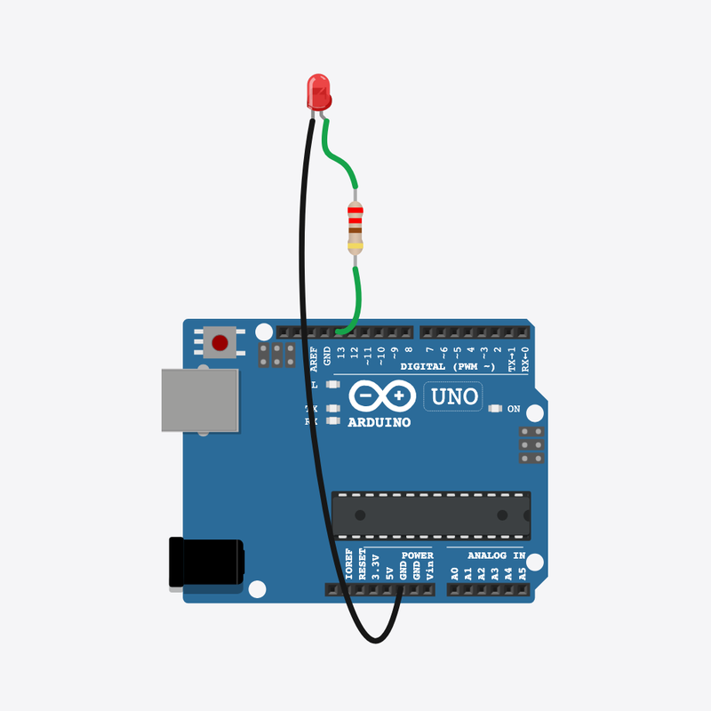
Electronic Candle circuit diagram

Pin connections

Part 1Part 2

Arduino

pin 13

Resistor

pin 2

Resistor

pin 1

LED

anode (+)

LED

cathode (-)

Arduino

GND

See it

Let's make a flickering candle!

A little light dances and flickers all by itself, just like a real flame.

Pretend candles and fake fireplaces flicker exactly like this!

The story

The problem

A steady blink looks like a robot. A real candle wobbles and flickers in surprise ways.

Think of it like

It's like a candle flame in the wind — it never dances the exact same way twice.

Meet the parts

It thinks and tells the light when to flicker.

Arduino

The brain

Loading part…

Slows the power down so the light does not get hurt.

Resistor

The protector

Loading part…

A tiny light that glows like a candle.

LED

The flame

Loading part…

How it works

1

A quick glow

The light turns on and waits a surprise amount of time — never the same blink twice.

digitalWrite(LED_PIN, HIGH);
delay(random(20, 80));
2

A quick dim

The light goes dim for another surprise wait, so the rhythm feels wobbly like a flame.

digitalWrite(LED_PIN, LOW);
delay(random(10, 40));
3

Sometimes a big flare

Once in a while the candle adds an extra bright glow — like the flame jumping! Then loop() flickers again.

if (random(0, 10) > 7) { ... longer glow ... }

Then loop back to step 1

Build the circuit

Follow these steps in order. Match the wires to the colors shown.

  1. 1

    Place Arduino

    Place the Arduino (uno) on the breadboard.

    Arduino placed — ready to build!

    Loading part…
  2. 2

    Place Resistor

    Place the Resistor (r1) on the breadboard.

    Loading part…
  3. 3

    Place LED

    Place the LED (led1) on the breadboard.

    Loading part…
  4. 4

    Connect Arduino pin 13 to Resistor (r1) 2

    Connect Arduino pin 13 to Resistor (r1) 2.

  5. 5

    Connect Resistor (r1) 1 to LED (led1) anode (+)

    Connect Resistor (r1) 1 to LED (led1) anode (+).

  6. 6

    Connect LED (led1) cathode (-) to Arduino GND

    Connect LED (led1) cathode (-) to Arduino GND.

Try it

  • Press the green Run button — the blinking should look wobbly, not perfect.
  • Watch for little bright flares, like a flame jumping up!

Peek at code

Get ready and shake the dice

void setup() {
  pinMode(LED_PIN, OUTPUT);
  randomSeed(analogRead(0));
}

setup() gets pin 13 ready, and randomSeed shakes up the surprise numbers so each run flickers differently.

The flicker

void loop() {
  digitalWrite(LED_PIN, HIGH);
  delay(random(20, 80));
  digitalWrite(LED_PIN, LOW);
  delay(random(10, 40));

Each wait is a surprise number, so the light flickers fast and slow — that is what makes it look alive.

The bonus flare

  if (random(0, 10) > 7) {
    digitalWrite(LED_PIN, HIGH);
    delay(random(100, 300));
  }

Once in a while this part adds a longer, brighter glow — like the candle flame leaping up.

Show full sketch (electronic-candle.ino)
const int LED_PIN = 13;
void setup() {
  pinMode(LED_PIN, OUTPUT);
  randomSeed(analogRead(0));
}
void loop() {
  digitalWrite(LED_PIN, HIGH);
  delay(random(20, 80));
  digitalWrite(LED_PIN, LOW);
  delay(random(10, 40));
  if (random(0, 10) > 7) {
    digitalWrite(LED_PIN, HIGH);
    delay(random(100, 300));
  }
}

Quick quiz

Q1. Which part runs again and again?

  • A. loop()
  • B. setup()
  • C. pinMode only
Why: Yes! loop() runs again and again, forever.

Q2. Why do we use random() inside delay() here?

  • A. So each wait is a different surprise length
  • B. To turn the light off forever
  • C. To read a button
Why: Yes! Surprise waits make the flicker look like a real flame.

Code lab — try on your own

  1. Make the flicker snappier — change random(20, 80) to random(10, 50) on line 8.

    Hint: Edit both numbers inside random(20, 80).

  2. Add a little note (comment) on the line that shakes up the surprise numbers.

    Hint: Type // and your words at the end of line 4.

Code walkthrough

A line-by-line tour of the sketch — the same steps as in Robot Gurukul Studio.

Program overview

Big idea

Every Arduino program has a top part, a setup() part that runs once, and a loop() part that runs again and again.

In this project

A light flickers with surprise timing so it looks like a real candle.

Tip

Read from the top to the bottom. Tap any word or line if you need help!

const int LED_PIN = 13;

setup()

Big idea

setup() runs one time when the board turns on.

In this project

It gets pin 13 ready for the light and shakes up the surprise numbers.

Why here

Things we do only once go inside setup().

void setup() {
  pinMode(LED_PIN, OUTPUT);
  randomSeed(analogRead(0));
}

loop()

Big idea

loop() runs again and again, forever.

In this project

This is where the light flickers fast and slow, never the same way twice.

Why here

Things that repeat go inside loop().

void loop() {
  digitalWrite(LED_PIN, HIGH);
  delay(random(20, 80));
  digitalWrite(LED_PIN, LOW);
  delay(random(10, 40));
  if (random(0, 10) > 7) {
    digitalWrite(LED_PIN, HIGH);
    delay(random(100, 300));
  }
}

Try this: Change a number inside loop(), then press Run to make the flicker faster or slower.

pinMode

Big idea

pinMode tells a pin if it will listen or push power out.

In this project

It makes pin 13 ready to push power to the light.

Why here

It goes in setup() because we only set it once.

  pinMode(LED_PIN, OUTPUT);

digitalWrite

Big idea

digitalWrite turns a pin ON or OFF.

In this project

ON lights up the candle, OFF makes it dim.

Why here

It goes in loop() so the light can keep flickering.

  digitalWrite(LED_PIN, HIGH);

analogRead

Big idea

analogRead reads a number from a pin — anything from 0 to 1023.

In this project

It reads a tiny bit of noise from pin 0 to help pick fresh surprise numbers.

Why here

In setup(), to shake up the randomness before the candle starts.

  randomSeed(analogRead(0));

delay

Big idea

delay means wait. Nothing else happens while it waits.

In this project

It waits a surprise amount of time so the flicker looks alive.

Why here

Right after we turn the light on or off.

  delay(random(20, 80));

random

Big idea

random picks a surprise number inside a range you choose.

In this project

It picks a different wait time each flicker, so no two blinks match.

Why here

In loop(), where we want a new surprise number every time.

  delay(random(20, 80));
Mission 10 · Stage 1

Mini Light Show

timed show sequences

Run a timed light show sequence on a bar graph.

Mini Light Show circuit diagram

Pin connections

Part 1Part 2

Arduino

pin 2

LED bar graph

A1

Arduino

pin 3

LED bar graph

A2

Arduino

pin 4

LED bar graph

A3

Arduino

pin 5

LED bar graph

A4

Arduino

pin 6

LED bar graph

A5

Arduino

pin 7

LED bar graph

A6

Arduino

pin 8

LED bar graph

A7

Arduino

pin 9

LED bar graph

A8

Arduino

pin 10

LED bar graph

A9

Arduino

pin 11

LED bar graph

A10

LED bar graph

C10

Arduino

GND

See it

Let's put on a light show!

Lights fill up, empty out, then flash all together — your own mini light show!

Stage lights and big signs play timed shows just like this!

The story

The problem

One pattern is fun, but a real show puts several fun parts together in order.

Think of it like

It's like a little dance routine — step one, step two, then a big finish!

Meet the parts

It thinks and runs the whole light show.

Arduino

The brain

Loading part…

Ten little lights in a line that put on the show.

LED bar graph

The row of lights

Loading part…

How it works

1

Part 1 — fill up

The lights turn on one by one, from left to right, until the whole row is glowing.

digitalWrite(FIRST_PIN + i, HIGH);
delay(80);
2

Hold the full row

All the lights stay on together for a moment before the next part.

delay(500);
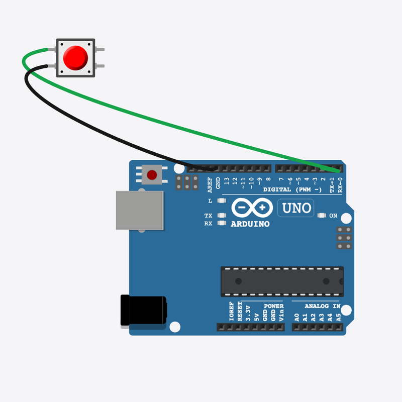
3

Part 2 — empty out

Now the lights turn off one by one, from right to left, until the row is dark.

digitalWrite(FIRST_PIN + i, LOW);
delay(80);
4

Part 3 — flash together

All the lights flash on and off three times — that is the big finish!

allOn(); delay(150); allOff(); delay(150);
5

Rest, then do it again

A nice long rest, then loop() jumps back and plays the whole show again!

delay(800);

Then loop back to step 1

Build the circuit

Follow these steps in order. Match the wires to the colors shown.

  1. 1

    Place Arduino

    Place the Arduino (uno) on the breadboard.

    Arduino placed — ready to build!

    Loading part…
  2. 2

    Place LED bar graph

    Place the LED bar graph (bar1) on the breadboard.

    Loading part…
  3. 3

    Connect Arduino pin 2 to LED bar graph (bar1) A1

    Connect Arduino pin 2 to LED bar graph (bar1) A1.

  4. 4

    Connect Arduino pin 3 to LED bar graph (bar1) A2

    Connect Arduino pin 3 to LED bar graph (bar1) A2.

  5. 5

    Connect Arduino pin 4 to LED bar graph (bar1) A3

    Connect Arduino pin 4 to LED bar graph (bar1) A3.

  6. 6

    Connect Arduino pin 5 to LED bar graph (bar1) A4

    Connect Arduino pin 5 to LED bar graph (bar1) A4.

  7. 7

    Connect Arduino pin 6 to LED bar graph (bar1) A5

    Connect Arduino pin 6 to LED bar graph (bar1) A5.

  8. 8

    Connect Arduino pin 7 to LED bar graph (bar1) A6

    Connect Arduino pin 7 to LED bar graph (bar1) A6.

  9. 9

    Connect Arduino pin 8 to LED bar graph (bar1) A7

    Connect Arduino pin 8 to LED bar graph (bar1) A7.

  10. 10

    Connect Arduino pin 9 to LED bar graph (bar1) A8

    Connect Arduino pin 9 to LED bar graph (bar1) A8.

  11. 11

    Connect Arduino pin 10 to LED bar graph (bar1) A9

    Connect Arduino pin 10 to LED bar graph (bar1) A9.

  12. 12

    Connect Arduino pin 11 to LED bar graph (bar1) A10

    Connect Arduino pin 11 to LED bar graph (bar1) A10.

  13. 13

    Connect LED bar graph (bar1) C10 to Arduino GND

    Connect LED bar graph (bar1) C10 to Arduino GND.

Try it

  • Press the green Run button — watch the full show: fill up, hold, empty, flash, rest.
  • Try to guess which part comes next!

Peek at code

The all-on and all-off helpers

void allOff() {
  for (int i = 0; i < NUM_LEDS; i++) {
    digitalWrite(FIRST_PIN + i, LOW);
  }
}
void allOn() {
  for (int i = 0; i < NUM_LEDS; i++) {
    digitalWrite(FIRST_PIN + i, HIGH);
  }
}

allOff() and allOn() use loops to switch all ten lights at once, so we don't write ten lines by hand.

Get all the lights ready

void setup() {
  for (int i = 0; i < NUM_LEDS; i++) {
    pinMode(FIRST_PIN + i, OUTPUT);
  }
}

setup() gets every light pin ready, one after another, so they can all glow.

The whole show

void loop() {
  for (int i = 0; i < NUM_LEDS; i++) {
    digitalWrite(FIRST_PIN + i, HIGH);
    delay(80);
  }
  delay(500);
  for (int i = NUM_LEDS - 1; i >= 0; i--) {
    digitalWrite(FIRST_PIN + i, LOW);
    delay(80);
  }
  delay(300);
  for (int n = 0; n < 3; n++) {
    allOn();
    delay(150);
    allOff();
    delay(150);
  }
  delay(800);
}

loop() plays the show in order: fill up, hold, empty out, flash three times, then rest.

Show full sketch (mini-light-show.ino)
const int FIRST_PIN = 2;
const int NUM_LEDS = 10;
void allOff() {
  for (int i = 0; i < NUM_LEDS; i++) {
    digitalWrite(FIRST_PIN + i, LOW);
  }
}
void allOn() {
  for (int i = 0; i < NUM_LEDS; i++) {
    digitalWrite(FIRST_PIN + i, HIGH);
  }
}
void setup() {
  for (int i = 0; i < NUM_LEDS; i++) {
    pinMode(FIRST_PIN + i, OUTPUT);
  }
}
void loop() {
  for (int i = 0; i < NUM_LEDS; i++) {
    digitalWrite(FIRST_PIN + i, HIGH);
    delay(80);
  }
  delay(500);
  for (int i = NUM_LEDS - 1; i >= 0; i--) {
    digitalWrite(FIRST_PIN + i, LOW);
    delay(80);
  }
  delay(300);
  for (int n = 0; n < 3; n++) {
    allOn();
    delay(150);
    allOff();
    delay(150);
  }
  delay(800);
}

Quick quiz

Q1. Which part runs again and again?

  • A. loop()
  • B. setup()
  • C. pinMode only
Why: Yes! loop() runs again and again, forever.

Q2. What makes this a light show?

  • A. Several timed parts that play in order
  • B. Just one wait
  • C. No lights at all
Why: Yes! Putting fun parts in order with waits makes the whole show.

Code lab — try on your own

  1. Speed up the wave — change delay(80) to delay(40) in both wave parts.

    Hint: These are the delay lines inside the loops that light the lights one by one.

  2. Add one more flash — change the flash count from n < 3 to n < 4.

    Hint: Find for (int n = 0; n < 3; n++).

Code walkthrough

A line-by-line tour of the sketch — the same steps as in Robot Gurukul Studio.

Program overview

Big idea

Every Arduino program has a top part, a setup() part that runs once, and a loop() part that runs again and again.

In this project

A row of ten lights fills up, empties out, and flashes — a real light show!

Tip

Read from the top to the bottom. Tap any word or line if you need help!

const int FIRST_PIN = 2;
const int NUM_LEDS = 10;
void allOff() {
  for (int i = 0; i < NUM_LEDS; i++) {
    digitalWrite(FIRST_PIN + i, LOW);
  }
}
void allOn() {
  for (int i = 0; i < NUM_LEDS; i++) {
    digitalWrite(FIRST_PIN + i, HIGH);
  }
}

setup()

Big idea

setup() runs one time when the board turns on.

In this project

It gets all ten light pins (starting at pin 2) ready.

Why here

Things we do only once go inside setup().

void setup() {
  for (int i = 0; i < NUM_LEDS; i++) {
    pinMode(FIRST_PIN + i, OUTPUT);
  }
}

loop()

Big idea

loop() runs again and again, forever.

In this project

This is where the whole light show plays from start to finish.

Why here

Things that repeat go inside loop().

void loop() {
  for (int i = 0; i < NUM_LEDS; i++) {
    digitalWrite(FIRST_PIN + i, HIGH);
    delay(80);
  }
  delay(500);
  for (int i = NUM_LEDS - 1; i >= 0; i--) {
    digitalWrite(FIRST_PIN + i, LOW);
    delay(80);
  }
  delay(300);
  for (int n = 0; n < 3; n++) {
    allOn();
    delay(150);
    allOff();
    delay(150);
  }
  delay(800);
}

Try this: Change a delay number inside loop(), then press Run to make the show faster or slower.

pinMode

Big idea

pinMode tells a pin if it will listen or push power out.

In this project

It makes each light pin ready to push power to a light.

Why here

It goes in setup() because we only set it once.

    pinMode(FIRST_PIN + i, OUTPUT);

digitalWrite

Big idea

digitalWrite turns a pin ON or OFF.

In this project

ON lights up a light, OFF turns it dark. Here it turns one light off.

Why here

It goes in loop() so the lights can keep changing.

    digitalWrite(FIRST_PIN + i, LOW);

delay

Big idea

delay means wait. Nothing else happens while it waits.

In this project

It sets how fast each part of the show plays.

Why here

Right after a light turns on or off.

    delay(80);

Stage 2: Inputs

digitalRead(), if statements

Stage 2 teaches inputs and decisions. Your Arduino can read buttons and switches with digitalRead(), then use if statements to choose what to do. You will build games, timers, and alarms.

Mission 11 · Stage 2

Push Button LED

digitalRead() reads an input pin

Toggle an LED with a pushbutton using internal pull-up resistor on pin 2.

Push Button LED circuit diagram

Pin connections

Part 1Part 2

Arduino

pin 2

Button

pin 1

Button

pin 2

Arduino

GND

Arduino

pin 13

Resistor

pin 1

Resistor

pin 2

LED

anode (+)

LED

cathode (-)

Arduino

GND

See it

Your code can listen to you!

Press the button and the light jumps on. Let go and it turns off!

Every keyboard key and game controller button works just like this.

The story

The problem

A light that only blinks cannot react to you. We need a way to read a button.

Think of it like

It's like asking "Is someone at the door?" before turning on the porch light.

Meet the parts

It thinks and decides when the light turns on.

Arduino

The brain

Loading part…

You press it to send a message to the brain.

Button

The button

Loading part…

Slows the power down so the light does not get hurt.

Resistor

The protector

Loading part…

It copies the button — on when you press, off when you let go.

LED

The light

Loading part…

How it works

1

Read the button

The board checks the button. With this wiring, a press counts as LOW, which means "pressed".

bool pressed = (digitalRead(BUTTON_PIN) == LOW);
2

Mirror to the LED

The light copies the button — on while you hold it, off when you let go.

digitalWrite(LED_PIN, pressed ? HIGH : LOW);
3

Small pause

A tiny wait keeps the reading steady, then loop() checks the button again.

delay(50);

Then loop back to step 1

Build the circuit

Follow these steps in order. Match the wires to the colors shown.

  1. 1

    Place Arduino

    Place the Arduino (uno) on the breadboard.

    Arduino placed — ready to build!

    Loading part…
  2. 2

    Place Button

    Place the Button (btn1) on the breadboard.

    Loading part…
  3. 3

    Place Resistor

    Place the Resistor (r1) on the breadboard.

    Loading part…
  4. 4

    Place LED

    Place the LED (led1) on the breadboard.

    Loading part…
  5. 5

    Connect Arduino pin 2 to Button (btn1) 1.l

    Connect Arduino pin 2 to Button (btn1) 1.l.

  6. 6

    Connect Button (btn1) 2.l to Arduino GND

    Connect Button (btn1) 2.l to Arduino GND.

  7. 7

    Connect Arduino pin 13 to Resistor (r1) 1

    Connect Arduino pin 13 to Resistor (r1) 1.

  8. 8

    Connect Resistor (r1) 2 to LED (led1) anode (+)

    Connect Resistor (r1) 2 to LED (led1) anode (+).

  9. 9

    Connect LED (led1) cathode (-) to Arduino GND

    Connect LED (led1) cathode (-) to Arduino GND.

Try it

  • Press and hold the button — the light should stay on!
  • Let go — the light turns off. Watch the screen messages too!

Peek at code

Getting the button ready

void setup() {
  pinMode(BUTTON_PIN, INPUT_PULLUP);
  pinMode(LED_PIN, OUTPUT);
  Serial.begin(9600);

INPUT_PULLUP makes pin 2 read HIGH until you press the button, which pulls it LOW.

Reading the button

void loop() {
  bool pressed = (digitalRead(BUTTON_PIN) == LOW);
  digitalWrite(LED_PIN, pressed ? HIGH : LOW);
  Serial.println(pressed ? "Button pressed" : "Button released");
  delay(50);

Each time through loop(), the board reads the button and copies it to the light and the screen.

Show full sketch (pushbutton.ino)
const int BUTTON_PIN = 2;
const int LED_PIN    = 13;
void setup() {
  pinMode(BUTTON_PIN, INPUT_PULLUP);
  pinMode(LED_PIN, OUTPUT);
  Serial.begin(9600);
}
void loop() {
  bool pressed = (digitalRead(BUTTON_PIN) == LOW);
  digitalWrite(LED_PIN, pressed ? HIGH : LOW);
  Serial.println(pressed ? "Button pressed" : "Button released");
  delay(50);
}

Quick quiz

Q1. Where does work that repeats go?

  • A. loop()
  • B. setup()
  • C. pinMode only
Why: Yes! loop() runs again and again.

Q2. When you press the button, what does the pin read?

  • A. LOW
  • B. HIGH
  • C. A random number
Why: Yes! Pressing connects the pin to ground, so it reads LOW.

Code lab — try on your own

  1. Make the button check slower — change delay(50) to delay(100).

    Hint: It's the last line inside loop(), line 12.

  2. Add a little note (comment) on the line that reads the button, line 9.

    Hint: Type // and your words at the end of line 9, like: // is the button pressed?

Code walkthrough

A line-by-line tour of the sketch — the same steps as in Robot Gurukul Studio.

Program overview

Big idea

Every Arduino program has a top part, a setup() part that runs once, and a loop() part that runs again and again.

In this project

When you press the button, the light turns on. Let go, and it turns off.

Tip

Read from the top to the bottom. Tap any word or line if you need help!

const int BUTTON_PIN = 2;
const int LED_PIN    = 13;

setup()

Big idea

setup() runs one time when the board turns on.

In this project

It gets the button ready to listen and pin 13 ready for the light.

Why here

Things we do only once go inside setup().

void setup() {
  pinMode(BUTTON_PIN, INPUT_PULLUP);
  pinMode(LED_PIN, OUTPUT);
  Serial.begin(9600);
}

loop()

Big idea

loop() runs again and again, forever.

In this project

It keeps checking the button and turns the light on or off.

Why here

Things that repeat go inside loop().

void loop() {
  bool pressed = (digitalRead(BUTTON_PIN) == LOW);
  digitalWrite(LED_PIN, pressed ? HIGH : LOW);
  Serial.println(pressed ? "Button pressed" : "Button released");
  delay(50);
}

Try this: Change a number inside loop(), then press Run to see what happens.

pinMode

Big idea

pinMode tells a pin if it will listen or push power out.

In this project

It makes pin 2 listen to the button and pin 13 push power to the light.

Why here

It goes in setup() because we only set it once.

  pinMode(BUTTON_PIN, INPUT_PULLUP);

digitalWrite

Big idea

digitalWrite turns a pin ON or OFF.

In this project

ON lights up the LED, OFF turns it dark.

Why here

It goes in loop() so the light can keep changing.

  digitalWrite(LED_PIN, pressed ? HIGH : LOW);

digitalRead

Big idea

digitalRead checks if a pin is ON or OFF.

In this project

It checks if you are pressing the button.

Why here

It goes in loop() so we can react the moment you press.

  bool pressed = (digitalRead(BUTTON_PIN) == LOW);

delay

Big idea

delay means wait. Nothing else happens while it waits.

In this project

A tiny wait makes the button read nice and steady.

Why here

Right after we check the button and set the light.

  delay(50);

begin

Big idea

Serial.begin opens a way for the board to send words to your computer screen.

In this project

It lets the program print "Button pressed" or "Button released".

Why here

It goes in setup() once, before we print anything.

  Serial.begin(9600);

println

Big idea

println sends a line of words to the screen.

In this project

It prints whether the button is pressed or let go.

Why here

In loop() so each new message shows on its own line.

  Serial.println(pressed ? "Button pressed" : "Button released");
Mission 12 · Stage 2

Push Button Buzzer

if statement branches output

Play a buzzer tone when the button is pressed using an if statement.

Push Button Buzzer circuit diagram

Pin connections

Part 1Part 2

Arduino

pin 2

Button

pin 1

Button

pin 2

Arduino

GND

Buzzer

pin 1 (+)

Arduino

pin 8

Buzzer

pin 2 (-)

Arduino

GND

See it

Let's make your code choose!

Press the button and the buzzer beeps. Let go and it stops — your code decides!

An "if" choice like this runs alarms, games, and robots every day.

The story

The problem

You want one thing to happen when the button is down, and another when it is up.

Think of it like

It's like saying "If it is raining, take an umbrella."

Meet the parts

It decides when the buzzer should beep.

Arduino

The brain

Loading part…

Press it to tell the brain to make sound.

Button

The button

Loading part…

It beeps when the brain says so.

Buzzer

The noise maker

Loading part…

How it works

1

Check button

This question is only true while you are holding the button down.

if (digitalRead(BUTTON_PIN) == LOW)
2

Play tone

Inside the if, the buzzer plays a beep at pitch 440.

tone(BUZZER_PIN, 440);
3

Otherwise stop

When you are not pressing, noTone keeps the buzzer quiet.

else { noTone(BUZZER_PIN); }

Then loop back to step 1

Build the circuit

Follow these steps in order. Match the wires to the colors shown.

  1. 1

    Place Arduino

    Place the Arduino (uno) on the breadboard.

    Arduino placed — ready to build!

    Loading part…
  2. 2

    Place Button

    Place the Button (btn1) on the breadboard.

    Loading part…
  3. 3

    Place Buzzer

    Place the Buzzer (bz1) on the breadboard.

    Loading part…
  4. 4

    Connect Arduino pin 2 to Button (btn1) 1.l

    Connect Arduino pin 2 to Button (btn1) 1.l.

  5. 5

    Connect Button (btn1) 2.l to Arduino GND

    Connect Button (btn1) 2.l to Arduino GND.

  6. 6

    Connect Buzzer (bz1) 1 to Arduino pin 8

    Connect Buzzer (bz1) 1 to Arduino pin 8.

  7. 7

    Connect Buzzer (bz1) 2 to Arduino GND

    Connect Buzzer (bz1) 2 to Arduino GND.

Try it

  • Press and hold — you should hear a steady beep.
  • Let go — silence! That is your "if" choice working.

Peek at code

Get input and output ready

void setup() {
  pinMode(BUTTON_PIN, INPUT_PULLUP);
  pinMode(BUZZER_PIN, OUTPUT);
}

The button is set to listen, and the buzzer pin is set to push sound out.

The if / else choice

void loop() {
  if (digitalRead(BUTTON_PIN) == LOW) {
    tone(BUZZER_PIN, 440);
  } else {
    noTone(BUZZER_PIN);
  }
  delay(20);
}

One path plays a beep, the other stops it — that is an if/else choice.

Show full sketch (pushbutton-buzzer.ino)
const int BUTTON_PIN = 2;
const int BUZZER_PIN = 8;
void setup() {
  pinMode(BUTTON_PIN, INPUT_PULLUP);
  pinMode(BUZZER_PIN, OUTPUT);
}
void loop() {
  if (digitalRead(BUTTON_PIN) == LOW) {
    tone(BUZZER_PIN, 440);
  } else {
    noTone(BUZZER_PIN);
  }
  delay(20);
}

Quick quiz

Q1. Where does work that repeats go?

  • A. loop()
  • B. setup()
  • C. pinMode only
Why: Yes! loop() runs again and again.

Q2. What happens when the button is NOT pressed?

  • A. The else part runs noTone() and the buzzer is quiet
  • B. setup() runs again
  • C. The beep plays forever
Why: Yes! The else part calls noTone() to stop the buzzer.

Code lab — try on your own

  1. Make the beep higher — change tone(BUZZER_PIN, 440) to use 880.

    Hint: It's inside the if, line 9.

  2. Add a note (comment) above the if line: // buzzer when pressed

    Hint: That's line 8.

Code walkthrough

A line-by-line tour of the sketch — the same steps as in Robot Gurukul Studio.

Program overview

Big idea

Every Arduino program has a top part, a setup() part that runs once, and a loop() part that runs again and again.

In this project

Hold the button and the buzzer plays a beep. Let go and it stops.

Tip

Read from the top to the bottom. Tap any word or line if you need help!

const int BUTTON_PIN = 2;
const int BUZZER_PIN = 8;

setup()

Big idea

setup() runs one time when the board turns on.

In this project

It gets the button ready to listen and pin 8 ready for the buzzer.

Why here

Things we do only once go inside setup().

void setup() {
  pinMode(BUTTON_PIN, INPUT_PULLUP);
  pinMode(BUZZER_PIN, OUTPUT);
}

loop()

Big idea

loop() runs again and again, forever.

In this project

It keeps asking "is the button pressed?" and beeps or stays quiet.

Why here

Things that repeat go inside loop().

void loop() {
  if (digitalRead(BUTTON_PIN) == LOW) {
    tone(BUZZER_PIN, 440);
  } else {
    noTone(BUZZER_PIN);
  }
  delay(20);
}

Try this: Change a number inside loop(), then press Run to see what happens.

pinMode

Big idea

pinMode tells a pin if it will listen or push power out.

In this project

It makes pin 2 listen to the button and pin 8 push sound to the buzzer.

Why here

It goes in setup() because we only set it once.

  pinMode(BUTTON_PIN, INPUT_PULLUP);

digitalRead

Big idea

digitalRead checks if a pin is ON or OFF.

In this project

It checks if you are pressing the button.

Why here

It goes in loop() so we can react the moment you press.

  if (digitalRead(BUTTON_PIN) == LOW) {

tone

Big idea

tone makes a buzzer play a beep at a chosen pitch.

In this project

When you press, it plays a 440 note.

Why here

It goes in loop() so it can play when the button is held.

    tone(BUZZER_PIN, 440);

noTone

Big idea

noTone stops the buzzer so it goes quiet.

In this project

When you let go of the button, the beep stops.

Why here

It goes in loop() to turn the sound off when not pressing.

    noTone(BUZZER_PIN);

delay

Big idea

delay means wait. Nothing else happens while it waits.

In this project

A tiny wait makes the button read nice and steady.

Why here

Right after we check the button and play or stop the sound.

  delay(20);
Mission 13 · Stage 2

Security Switch

switch state vs momentary button

Use a slide switch to toggle an LED on and off.

Security Switch circuit diagram

Pin connections

Part 1Part 2

Slide switch

pin 2

Arduino

pin 2

Slide switch

pin 1

Arduino

GND

Arduino

pin 13

Resistor

pin 1

Resistor

pin 2

LED

anode (+)

LED

cathode (-)

Arduino

GND

See it

Let's make a switch that remembers!

Slide it one way and the light stays on. Slide it back and it stays off.

The light switches on your walls work just like this — they stay where you leave them.

The story

The problem

A button only works while you hold it. Sometimes you want the light to stay on by itself.

Think of it like

A button is like a doorbell. A slide switch is like a wall light switch that stays put.

Meet the parts

It checks the switch and decides about the light.

Arduino

The brain

Loading part…

Slide it and it stays on or off all by itself.

Slide switch

The switch

Loading part…

Slows the power down so the light does not get hurt.

Resistor

The protector

Loading part…

It shows which way the switch is set.

LED

The light

Loading part…

How it works

1

Read switch position

It reads the switch the same way as a button — but the switch stays put until you move it.

bool active = (digitalRead(SWITCH_PIN) == LOW);
2

Show state on LED

The light stays on while the switch is ON — you do not need to hold anything.

digitalWrite(LED_PIN, active ? HIGH : LOW);

Then loop back to step 1

Build the circuit

Follow these steps in order. Match the wires to the colors shown.

  1. 1

    Place Arduino

    Place the Arduino (uno) on the breadboard.

    Arduino placed — ready to build!

    Loading part…
  2. 2

    Place Slide switch

    Place the Slide switch (sw1) on the breadboard.

    Loading part…
  3. 3

    Place Resistor

    Place the Resistor (r1) on the breadboard.

    Loading part…
  4. 4

    Place LED

    Place the LED (led1) on the breadboard.

    Loading part…
  5. 5

    Connect Slide switch (sw1) 2 to Arduino pin 2

    Connect Slide switch (sw1) 2 to Arduino pin 2.

  6. 6

    Connect Slide switch (sw1) 1 to Arduino GND

    Connect Slide switch (sw1) 1 to Arduino GND.

  7. 7

    Connect Arduino pin 13 to Resistor (r1) 1

    Connect Arduino pin 13 to Resistor (r1) 1.

  8. 8

    Connect Resistor (r1) 2 to LED (led1) anode (+)

    Connect Resistor (r1) 2 to LED (led1) anode (+).

  9. 9

    Connect LED (led1) cathode (-) to Arduino GND

    Connect LED (led1) cathode (-) to Arduino GND.

Try it

  • Slide the switch — the light should stay on or off.
  • Compare it to the button: no need to keep holding it!

Peek at code

Getting the switch ready

void setup() {
  pinMode(SWITCH_PIN, INPUT_PULLUP);
  pinMode(LED_PIN, OUTPUT);
  Serial.begin(9600);
  Serial.println("Slide Switch Demo");
}

We set up the switch pin the same way as a button — the part just acts differently.

Read and copy

void loop() {
  bool active = (digitalRead(SWITCH_PIN) == LOW);
  digitalWrite(LED_PIN, active ? HIGH : LOW);
  Serial.println(active ? "Switch ON  -> LED ON" : "Switch OFF -> LED OFF");
  delay(100);
}

loop() keeps checking the switch, and the light matches where you left it.

Show full sketch (slide-switch.ino)
const int SWITCH_PIN = 2;
const int LED_PIN    = 13;
void setup() {
  pinMode(SWITCH_PIN, INPUT_PULLUP);
  pinMode(LED_PIN, OUTPUT);
  Serial.begin(9600);
  Serial.println("Slide Switch Demo");
}
void loop() {
  bool active = (digitalRead(SWITCH_PIN) == LOW);
  digitalWrite(LED_PIN, active ? HIGH : LOW);
  Serial.println(active ? "Switch ON  -> LED ON" : "Switch OFF -> LED OFF");
  delay(100);
}

Quick quiz

Q1. Where does work that repeats go?

  • A. loop()
  • B. setup()
  • C. pinMode only
Why: Yes! loop() runs again and again.

Q2. How is a slide switch different from a push button?

  • A. It stays where you slide it
  • B. It only works in setup()
  • C. It does not use digitalRead()
Why: Yes! A switch stays on or off; a button pops back when you let go.

Code lab — try on your own

  1. Make the switch check slower — change delay(100) to delay(200).

    Hint: It's the last line inside loop().

  2. Add a note (comment) on line 10: // switch ON when LOW

    Hint: That's the line with active = digitalRead.

Code walkthrough

A line-by-line tour of the sketch — the same steps as in Robot Gurukul Studio.

Program overview

Big idea

Every Arduino program has a top part, a setup() part that runs once, and a loop() part that runs again and again.

In this project

Slide the switch and a light turns on or off — and it stays that way.

Tip

Read from the top to the bottom. Tap any word or line if you need help!

const int SWITCH_PIN = 2;
const int LED_PIN    = 13;

setup()

Big idea

setup() runs one time when the board turns on.

In this project

It gets the switch ready to listen and pin 13 ready for the light.

Why here

Things we do only once go inside setup().

void setup() {
  pinMode(SWITCH_PIN, INPUT_PULLUP);
  pinMode(LED_PIN, OUTPUT);
  Serial.begin(9600);
  Serial.println("Slide Switch Demo");
}

loop()

Big idea

loop() runs again and again, forever.

In this project

It keeps checking where the switch is and turns the light on or off.

Why here

Things that repeat go inside loop().

void loop() {
  bool active = (digitalRead(SWITCH_PIN) == LOW);
  digitalWrite(LED_PIN, active ? HIGH : LOW);
  Serial.println(active ? "Switch ON  -> LED ON" : "Switch OFF -> LED OFF");
  delay(100);
}

Try this: Change a number inside loop(), then press Run to see what happens.

pinMode

Big idea

pinMode tells a pin if it will listen or push power out.

In this project

It makes pin 2 listen to the switch and pin 13 push power to the light.

Why here

It goes in setup() because we only set it once.

  pinMode(SWITCH_PIN, INPUT_PULLUP);

digitalWrite

Big idea

digitalWrite turns a pin ON or OFF.

In this project

ON lights up the LED, OFF turns it dark.

Why here

It goes in loop() so the light can keep changing.

  digitalWrite(LED_PIN, active ? HIGH : LOW);

digitalRead

Big idea

digitalRead checks if a pin is ON or OFF.

In this project

It checks which way the switch is sliding.

Why here

It goes in loop() so we can react when the switch moves.

  bool active = (digitalRead(SWITCH_PIN) == LOW);

delay

Big idea

delay means wait. Nothing else happens while it waits.

In this project

A small wait makes the switch read nice and steady.

Why here

Right after we check the switch and set the light.

  delay(100);

begin

Big idea

Serial.begin opens a way for the board to send words to your computer screen.

In this project

It lets the program print whether the switch is on or off.

Why here

It goes in setup() once, before we print anything.

  Serial.begin(9600);

println

Big idea

println sends a line of words to the screen.

In this project

It prints "Switch ON" or "Switch OFF".

Why here

In loop() so each new message shows on its own line.

  Serial.println("Slide Switch Demo");
Mission 14 · Stage 2

Toggle Button

edge detection and toggle latch

Each button press toggles an LED on or off using edge detection.

Toggle Button circuit diagram

Pin connections

Part 1Part 2

Arduino

pin 2

Button

pin 1

Button

pin 2

Arduino

GND

Arduino

pin 13

Resistor

pin 1

Resistor

pin 2

LED

anode (+)

LED

cathode (-)

Arduino

GND

See it

Let's make a tap turn it on and off!

Tap once and the light glows. Tap again and it goes dark — like a real power button.

The power buttons on TVs and game consoles flip on and off just like this.

The story

The problem

Holding a button keeps the light on only while you hold. We want one tap to flip it and keep it.

Think of it like

Like flipping a coin once each time you tap — not while your finger rests on it.

Meet the parts

It remembers the light and flips it on each tap.

Arduino

The brain

Loading part…

Each tap flips the light to the other state.

Button

The button

Loading part…

Slows the power down so the light does not get hurt.

Resistor

The protector

Loading part…

It stays on until your next tap.

LED

The light

Loading part…

How it works

1

Remember last reading

We compare this new reading with lastReading to see if something changed.

bool reading = digitalRead(BUTTON_PIN);
2

Catch the press moment

Going from not-pressed to pressed means you just tapped — that is one flip.

if (lastReading == HIGH && reading == LOW)
3

Flip and remember

ledOn remembers the light, so it stays on or off between taps.

ledOn = !ledOn;
digitalWrite(LED_PIN, ledOn ? HIGH : LOW);

Then loop back to step 1

Build the circuit

Follow these steps in order. Match the wires to the colors shown.

  1. 1

    Place Arduino

    Place the Arduino (uno) on the breadboard.

    Arduino placed — ready to build!

    Loading part…
  2. 2

    Place Button

    Place the Button (btn1) on the breadboard.

    Loading part…
  3. 3

    Place Resistor

    Place the Resistor (r1) on the breadboard.

    Loading part…
  4. 4

    Place LED

    Place the LED (led1) on the breadboard.

    Loading part…
  5. 5

    Connect Arduino pin 2 to Button (btn1) 1.l

    Connect Arduino pin 2 to Button (btn1) 1.l.

  6. 6

    Connect Button (btn1) 2.l to Arduino GND

    Connect Button (btn1) 2.l to Arduino GND.

  7. 7

    Connect Arduino pin 13 to Resistor (r1) 1

    Connect Arduino pin 13 to Resistor (r1) 1.

  8. 8

    Connect Resistor (r1) 2 to LED (led1) anode (+)

    Connect Resistor (r1) 2 to LED (led1) anode (+).

  9. 9

    Connect LED (led1) cathode (-) to Arduino GND

    Connect LED (led1) cathode (-) to Arduino GND.

Try it

  • Tap the button — the light flips with each tap.
  • Hold it down — it should NOT flicker on and off fast.

Peek at code

Memory boxes

bool ledOn = false;
bool lastReading = HIGH;

ledOn remembers the light; lastReading remembers what the button looked like before.

Catching the press

void loop() {
  bool reading = digitalRead(BUTTON_PIN);
  if (lastReading == HIGH && reading == LOW) {
    ledOn = !ledOn;
    digitalWrite(LED_PIN, ledOn ? HIGH : LOW);
  }
  lastReading = reading;
  delay(10);
}

Only a fresh press flips the light — holding the button does nothing extra.

Show full sketch (toggle-button.ino)
const int BUTTON_PIN = 2;
const int LED_PIN = 13;
bool ledOn = false;
bool lastReading = HIGH;
void setup() {
  pinMode(BUTTON_PIN, INPUT_PULLUP);
  pinMode(LED_PIN, OUTPUT);
  digitalWrite(LED_PIN, LOW);
}
void loop() {
  bool reading = digitalRead(BUTTON_PIN);
  if (lastReading == HIGH && reading == LOW) {
    ledOn = !ledOn;
    digitalWrite(LED_PIN, ledOn ? HIGH : LOW);
  }
  lastReading = reading;
  delay(10);
}

Quick quiz

Q1. Where does work that repeats go?

  • A. loop()
  • B. setup()
  • C. pinMode only
Why: Yes! loop() runs again and again.

Q2. Why do we check lastReading == HIGH && reading == LOW?

  • A. To catch the exact moment of a press
  • B. To make the light brighter
  • C. To run setup() again
Why: Yes! It fires once per press, not the whole time you hold.

Code lab — try on your own

  1. Make button checks snappier — change delay(10) to delay(5).

    Hint: It's the last line inside loop().

  2. Add a note (comment) on the line ledOn = !ledOn that says "flip the light".

    Hint: That's line 13.

Code walkthrough

A line-by-line tour of the sketch — the same steps as in Robot Gurukul Studio.

Program overview

Big idea

Every Arduino program has a top part, a setup() part that runs once, and a loop() part that runs again and again.

In this project

One tap turns the light on. The next tap turns it off.

Tip

Read from the top to the bottom. Tap any word or line if you need help!

const int BUTTON_PIN = 2;
const int LED_PIN = 13;
bool ledOn = false;
bool lastReading = HIGH;

setup()

Big idea

setup() runs one time when the board turns on.

In this project

It gets the button ready to listen, pin 13 ready for the light, and starts the light off.

Why here

Things we do only once go inside setup().

void setup() {
  pinMode(BUTTON_PIN, INPUT_PULLUP);
  pinMode(LED_PIN, OUTPUT);
  digitalWrite(LED_PIN, LOW);
}

loop()

Big idea

loop() runs again and again, forever.

In this project

It watches for the moment you press, then flips the light.

Why here

Things that repeat go inside loop().

void loop() {
  bool reading = digitalRead(BUTTON_PIN);
  if (lastReading == HIGH && reading == LOW) {
    ledOn = !ledOn;
    digitalWrite(LED_PIN, ledOn ? HIGH : LOW);
  }
  lastReading = reading;
  delay(10);
}

Try this: Change a number inside loop(), then press Run to see what happens.

pinMode

Big idea

pinMode tells a pin if it will listen or push power out.

In this project

It makes pin 2 listen to the button and pin 13 push power to the light.

Why here

It goes in setup() because we only set it once.

  pinMode(BUTTON_PIN, INPUT_PULLUP);

digitalWrite

Big idea

digitalWrite turns a pin ON or OFF.

In this project

It starts the light off so we begin in a known state.

Why here

This one is in setup() so the light begins dark.

  digitalWrite(LED_PIN, LOW);

digitalRead

Big idea

digitalRead checks if a pin is ON or OFF.

In this project

It reads the button each loop to spot a fresh press.

Why here

It goes in loop() so we can catch the moment you press.

  bool reading = digitalRead(BUTTON_PIN);

delay

Big idea

delay means wait. Nothing else happens while it waits.

In this project

A tiny wait keeps button reads steady and clean.

Why here

Right after we check the button.

  delay(10);
Mission 15 · Stage 2

Reaction Timer

millis() with if conditions

Measure button reaction time with millis() after a random GO signal.

Reaction Timer circuit diagram

Pin connections

Part 1Part 2

Arduino

pin 2

Button

pin 1

Button

pin 2

Arduino

GND

Arduino

pin 13

Resistor

pin 1

Resistor

pin 2

GO LED

anode (+)

GO LED

cathode (-)

Arduino

GND

See it

Let's time how fast you are!

Wait… wait… GO! Press as fast as you can and see your speed in numbers.

Game timers and sports clocks use this same trick to count time.

The story

The problem

If we used delay to wait, the program would freeze. We need a clock that keeps ticking.

Think of it like

millis() is like a stopwatch that never stops counting.

Meet the parts

It runs the clock and times your press.

Arduino

The brain

Loading part…

Press it the second the GO light turns on.

Button

The button

Loading part…

Slows the power down so the GO light does not get hurt.

Resistor

The protector

Loading part…

It tells you the exact moment to press.

GO LED

The GO light

Loading part…

How it works

1

Wait a surprise time

Instead of freezing, we just check the clock until it reaches the GO time.

if (state == WAIT && millis() >= waitUntil)
2

Show GO

The light turns on and we save the exact moment in goTime.

digitalWrite(GO_LED, HIGH);
goTime = millis();
3

Measure your speed

Take the time now and subtract goTime to find how fast you pressed.

reaction = millis() - goTime;

Then loop back to step 1

Build the circuit

Follow these steps in order. Match the wires to the colors shown.

  1. 1

    Place Arduino

    Place the Arduino (uno) on the breadboard.

    Arduino placed — ready to build!

    Loading part…
  2. 2

    Place Button

    Place the Button (btn1) on the breadboard.

    Loading part…
  3. 3

    Place Resistor

    Place the Resistor (r1) on the breadboard.

    Loading part…
  4. 4

    Place GO LED

    Place the GO LED (led1) on the breadboard.

    Loading part…
  5. 5

    Connect Arduino pin 2 to Button (btn1) 1.l

    Connect Arduino pin 2 to Button (btn1) 1.l.

  6. 6

    Connect Button (btn1) 2.l to Arduino GND

    Connect Button (btn1) 2.l to Arduino GND.

  7. 7

    Connect Arduino pin 13 to Resistor (r1) 1

    Connect Arduino pin 13 to Resistor (r1) 1.

  8. 8

    Connect Resistor (r1) 2 to GO LED (led1) anode (+)

    Connect Resistor (r1) 2 to GO LED (led1) anode (+).

  9. 9

    Connect GO LED (led1) cathode (-) to Arduino GND

    Connect GO LED (led1) cathode (-) to Arduino GND.

Try it

  • Open the Serial Monitor, wait for GO!, then press fast.
  • Read your reaction time in milliseconds — smaller is faster!

Peek at code

The game modes

enum State { WAIT, GO, SCORED };
State state = WAIT;
unsigned long goTime = 0;
unsigned long waitUntil = 0;

The game has three modes: WAIT, GO, and SCORED. The program moves between them.

scheduleWait()

void scheduleWait() {
  digitalWrite(GO_LED, LOW);
  waitUntil = millis() + random(2000, 5000);
  state = WAIT;
}

This sets a surprise future time for GO, without freezing the program.

Timing your press

void loop() {
  if (state == WAIT && millis() >= waitUntil) {
    digitalWrite(GO_LED, HIGH);
    goTime = millis();
    state = GO;
    Serial.println("GO! Press the button!");
  }
  if (state == GO && digitalRead(BUTTON_PIN) == LOW) {
    unsigned long reaction = millis() - goTime;
    Serial.print("Reaction: ");
    Serial.print(reaction);
    Serial.println(" ms");
    state = SCORED;
    delay(2000);
    scheduleWait();
  }
  delay(10);

loop() watches the clock to start GO, then times how fast you pressed.

Show full sketch (reaction-timer.ino)
const int BUTTON_PIN = 2;
const int GO_LED = 13;
enum State { WAIT, GO, SCORED };
State state = WAIT;
unsigned long goTime = 0;
unsigned long waitUntil = 0;
void scheduleWait() {
  digitalWrite(GO_LED, LOW);
  waitUntil = millis() + random(2000, 5000);
  state = WAIT;
}
void setup() {
  pinMode(BUTTON_PIN, INPUT_PULLUP);
  pinMode(GO_LED, OUTPUT);
  Serial.begin(9600);
  randomSeed(analogRead(0));
  scheduleWait();
  Serial.println("Reaction Timer — wait for GO!");
}
void loop() {
  if (state == WAIT && millis() >= waitUntil) {
    digitalWrite(GO_LED, HIGH);
    goTime = millis();
    state = GO;
    Serial.println("GO! Press the button!");
  }
  if (state == GO && digitalRead(BUTTON_PIN) == LOW) {
    unsigned long reaction = millis() - goTime;
    Serial.print("Reaction: ");
    Serial.print(reaction);
    Serial.println(" ms");
    state = SCORED;
    delay(2000);
    scheduleWait();
  }
  delay(10);
}

Quick quiz

Q1. Where does work that repeats go?

  • A. loop()
  • B. setup()
  • C. pinMode only
Why: Yes! loop() runs again and again.

Q2. Why use millis() instead of delay() while waiting?

  • A. millis() lets the program keep checking things
  • B. millis() is louder
  • C. delay() reads buttons faster
Why: Yes! millis() counts time without freezing the program.

Code lab — try on your own

  1. Make the waits shorter — change random(2000, 5000) to random(1000, 3000).

    Hint: It's inside scheduleWait(), line 9.

  2. Add a note (comment) on line 28 that says this is the time since GO.

    Hint: That's the reaction = millis() - goTime line.

Code walkthrough

A line-by-line tour of the sketch — the same steps as in Robot Gurukul Studio.

Program overview

Big idea

Every Arduino program has a top part, a setup() part that runs once, and a loop() part that runs again and again.

In this project

The light waits, then says GO. You press fast, and it shows how quick you were.

Tip

Read from the top to the bottom. Tap any word or line if you need help!

const int BUTTON_PIN = 2;
const int GO_LED = 13;
enum State { WAIT, GO, SCORED };
State state = WAIT;
unsigned long goTime = 0;
unsigned long waitUntil = 0;
void scheduleWait() {
  digitalWrite(GO_LED, LOW);
  waitUntil = millis() + random(2000, 5000);
  state = WAIT;
}

setup()

Big idea

setup() runs one time when the board turns on.

In this project

It gets the button and GO light ready, mixes up the randomness, and starts the first wait.

Why here

Things we do only once go inside setup().

void setup() {
  pinMode(BUTTON_PIN, INPUT_PULLUP);
  pinMode(GO_LED, OUTPUT);
  Serial.begin(9600);
  randomSeed(analogRead(0));
  scheduleWait();
  Serial.println("Reaction Timer — wait for GO!");
}

loop()

Big idea

loop() runs again and again, forever.

In this project

It checks the clock, shows GO at the right time, and times your press.

Why here

Things that repeat go inside loop().

void loop() {
  if (state == WAIT && millis() >= waitUntil) {
    digitalWrite(GO_LED, HIGH);
    goTime = millis();
    state = GO;
    Serial.println("GO! Press the button!");
  }
  if (state == GO && digitalRead(BUTTON_PIN) == LOW) {
    unsigned long reaction = millis() - goTime;
    Serial.print("Reaction: ");
    Serial.print(reaction);
    Serial.println(" ms");
    state = SCORED;
    delay(2000);
    scheduleWait();
  }
  delay(10);
}

Try this: Change a number inside loop(), then press Run to see what happens.

pinMode

Big idea

pinMode tells a pin if it will listen or push power out.

In this project

It makes pin 2 listen to the button and pin 13 push power to the GO light.

Why here

It goes in setup() because we only set it once.

  pinMode(BUTTON_PIN, INPUT_PULLUP);

digitalWrite

Big idea

digitalWrite turns a pin ON or OFF.

In this project

It turns the GO light off again to get ready for the next round.

Why here

It is used when we set up the next wait.

  digitalWrite(GO_LED, LOW);

digitalRead

Big idea

digitalRead checks if a pin is ON or OFF.

In this project

It checks if you pressed the button after GO.

Why here

It goes in loop() so we can catch your press.

  if (state == GO && digitalRead(BUTTON_PIN) == LOW) {

analogRead

Big idea

analogRead reads a number from a pin, from 0 up to 1023.

In this project

It reads a wiggly number from an empty pin to mix up the randomness.

Why here

In setup() so each game has a different GO time.

  randomSeed(analogRead(0));

delay

Big idea

delay means wait. Nothing else happens while it waits.

In this project

It pauses for a moment after showing your score, before the next round.

Why here

Right after we print your reaction time.

    delay(2000);

millis

Big idea

millis counts how many milliseconds the board has been on, like a stopwatch.

In this project

It marks when GO appears and when you press, so we can find the difference.

Why here

It lets us time things without stopping the whole program.

  waitUntil = millis() + random(2000, 5000);

random

Big idea

random picks a surprise number for you.

In this project

It picks how long to wait before GO, so you cannot guess it.

Why here

When we set up each new round.

  waitUntil = millis() + random(2000, 5000);

begin

Big idea

Serial.begin opens a way for the board to send words to your computer screen.

In this project

It lets the program print GO and your reaction time.

Why here

It goes in setup() once, before we print anything.

  Serial.begin(9600);

print

Big idea

print sends words to the screen but stays on the same line.

In this project

It prints "Reaction: " right before your number.

Why here

In loop() so the label and number sit together.

    Serial.print("Reaction: ");

println

Big idea

println sends a line of words to the screen.

In this project

It prints the GO message and starts a new line.

Why here

In setup() so you see the start message.

  Serial.println("Reaction Timer — wait for GO!");
Mission 16 · Stage 2

Quiz Buzzer

multiple inputs and first-wins logic

Two players race — first button press wins and locks out the other.

Quiz Buzzer circuit diagram

Pin connections

Part 1Part 2

Arduino

pin 2

Player A button

pin 1

Player A button

pin 2

Arduino

GND

Arduino

pin 3

Player B button

pin 1

Player B button

pin 2

Arduino

GND

Arduino

pin 12

Resistor A

pin 2

Resistor A

pin 1

Player A LED

anode (+)

Player A LED

cathode (-)

Arduino

GND

Arduino

pin 13

Resistor B

pin 2

Resistor B

pin 1

Player B LED

anode (+)

Player B LED

cathode (-)

Arduino

GND

Arduino

pin 8

Buzzer

pin 1 (+)

Buzzer

pin 2 (-)

Arduino

GND

See it

Let's see who is fastest!

Two players, two buttons — the first to press wins and the other is locked out.

TV quiz shows use this exact "first to buzz wins" idea.

The story

The problem

Two players might press at almost the same time. We need a rule for who wins.

Think of it like

Like slapping the buzzer in a quiz — the first hand down locks the round.

Meet the parts

It decides who pressed first and locks the round.

Arduino

The referee

Loading part…

Press it to buzz in for Player A.

Player A button

Player A's button

Loading part…

Press it to buzz in for Player B.

Player B button

Player B's button

Loading part…

It glows when Player A wins.

Player A LED

Player A's light

Loading part…

It glows when Player B wins.

Player B LED

Player B's light

Loading part…

Slows the power so Player A's light stays safe.

Resistor A

The protector

Loading part…

Slows the power so Player B's light stays safe.

Resistor B

The protector

Loading part…

It beeps to cheer for the winner.

Buzzer

The noise maker

Loading part…

How it works

1

Is the round still open?

We only accept a press while the round is not locked yet.

if (!locked && digitalRead(BTN_A) == LOW)
2

Player A wins

The first press locks the round so Player B cannot win this time.

locked = true;
digitalWrite(LED_A, HIGH);
tone(BUZZER, 523);
3

Start a new round

Once both buttons are let go, the round clears and is ready again.

resetRound();

Then loop back to step 1

Build the circuit

Follow these steps in order. Match the wires to the colors shown.

  1. 1

    Place Arduino

    Place the Arduino (uno) on the breadboard.

    Arduino placed — ready to build!

    Loading part…
  2. 2

    Place Player A button

    Place the Player A button (btnA) on the breadboard.

    Loading part…
  3. 3

    Place Player B button

    Place the Player B button (btnB) on the breadboard.

    Loading part…
  4. 4

    Place Player A LED

    Place the Player A LED (ledA) on the breadboard.

    Loading part…
  5. 5

    Place Player B LED

    Place the Player B LED (ledB) on the breadboard.

    Loading part…
  6. 6

    Place Resistor A

    Place the Resistor A (rA) on the breadboard.

    Loading part…
  7. 7

    Place Resistor B

    Place the Resistor B (rB) on the breadboard.

    Loading part…
  8. 8

    Place Buzzer

    Place the Buzzer (bz1) on the breadboard.

    Loading part…
  9. 9

    Connect Arduino pin 2 to Player A button (btnA) 1.l

    Connect Arduino pin 2 to Player A button (btnA) 1.l.

  10. 10

    Connect Player A button (btnA) 2.l to Arduino GND

    Connect Player A button (btnA) 2.l to Arduino GND.

  11. 11

    Connect Arduino pin 3 to Player B button (btnB) 1.l

    Connect Arduino pin 3 to Player B button (btnB) 1.l.

  12. 12

    Connect Player B button (btnB) 2.l to Arduino GND

    Connect Player B button (btnB) 2.l to Arduino GND.

  13. 13

    Connect Arduino pin 12 to Resistor A (rA) 2

    Connect Arduino pin 12 to Resistor A (rA) 2.

  14. 14

    Connect Resistor A (rA) 1 to Player A LED (ledA) anode (+)

    Connect Resistor A (rA) 1 to Player A LED (ledA) anode (+).

  15. 15

    Connect Player A LED (ledA) cathode (-) to Arduino GND

    Connect Player A LED (ledA) cathode (-) to Arduino GND.

  16. 16

    Connect Arduino pin 13 to Resistor B (rB) 2

    Connect Arduino pin 13 to Resistor B (rB) 2.

  17. 17

    Connect Resistor B (rB) 1 to Player B LED (ledB) anode (+)

    Connect Resistor B (rB) 1 to Player B LED (ledB) anode (+).

  18. 18

    Connect Player B LED (ledB) cathode (-) to Arduino GND

    Connect Player B LED (ledB) cathode (-) to Arduino GND.

  19. 19

    Connect Arduino pin 8 to Buzzer (bz1) 1

    Connect Arduino pin 8 to Buzzer (bz1) 1.

  20. 20

    Connect Buzzer (bz1) 2 to Arduino GND

    Connect Buzzer (bz1) 2 to Arduino GND.

Try it

  • Player A uses the red button. Player B uses the blue button.
  • The first press lights that player's LED — the other does nothing until reset.

Peek at code

The lock

bool locked = false;
void resetRound() {
  locked = false;
  digitalWrite(LED_A, LOW);
  digitalWrite(LED_B, LOW);
  noTone(BUZZER);
}

locked is the game rule — once it is true, other presses are ignored.

First press wins

void loop() {
  if (!locked && digitalRead(BTN_A) == LOW) {
    locked = true;
    digitalWrite(LED_A, HIGH);
    tone(BUZZER, 523, 500);
  } else if (!locked && digitalRead(BTN_B) == LOW) {
    locked = true;
    digitalWrite(LED_B, HIGH);
    tone(BUZZER, 440, 500);
  }
  if (locked && digitalRead(BTN_A) == HIGH && digitalRead(BTN_B) == HIGH) {
    delay(1500);
    resetRound();
  }
  delay(20);
}

We check Player A, then Player B. resetRound() clears the lights and the lock.

Show full sketch (quiz-buzzer.ino)
const int BTN_A = 2;
const int BTN_B = 3;
const int LED_A = 12;
const int LED_B = 13;
const int BUZZER = 8;
bool locked = false;
void resetRound() {
  locked = false;
  digitalWrite(LED_A, LOW);
  digitalWrite(LED_B, LOW);
  noTone(BUZZER);
}
void setup() {
  pinMode(BTN_A, INPUT_PULLUP);
  pinMode(BTN_B, INPUT_PULLUP);
  pinMode(LED_A, OUTPUT);
  pinMode(LED_B, OUTPUT);
  pinMode(BUZZER, OUTPUT);
  resetRound();
}
void loop() {
  if (!locked && digitalRead(BTN_A) == LOW) {
    locked = true;
    digitalWrite(LED_A, HIGH);
    tone(BUZZER, 523, 500);
  } else if (!locked && digitalRead(BTN_B) == LOW) {
    locked = true;
    digitalWrite(LED_B, HIGH);
    tone(BUZZER, 440, 500);
  }
  if (locked && digitalRead(BTN_A) == HIGH && digitalRead(BTN_B) == HIGH) {
    delay(1500);
    resetRound();
  }
  delay(20);
}

Quick quiz

Q1. Where does work that repeats go?

  • A. loop()
  • B. setup()
  • C. pinMode only
Why: Yes! loop() runs again and again.

Q2. What does locked = true stop?

  • A. The other player winning after the first press
  • B. The buzzer from ever working
  • C. setup() from running
Why: Yes! The first press locks the round for that player.

Code lab — try on your own

  1. Make rounds start sooner — change delay(1500) to delay(800).

    Hint: That's line 32.

  2. Add a note (comment) on line 23: // Player A wins first

    Hint: It's inside the first if block.

Code walkthrough

A line-by-line tour of the sketch — the same steps as in Robot Gurukul Studio.

Program overview

Big idea

Every Arduino program has a top part, a setup() part that runs once, and a loop() part that runs again and again.

In this project

Two players race. The first to press lights their LED and beeps — the other is locked out.

Tip

Read from the top to the bottom. Tap any word or line if you need help!

const int BTN_A = 2;
const int BTN_B = 3;
const int LED_A = 12;
const int LED_B = 13;
const int BUZZER = 8;
bool locked = false;
void resetRound() {
  locked = false;
  digitalWrite(LED_A, LOW);
  digitalWrite(LED_B, LOW);
  noTone(BUZZER);
}

setup()

Big idea

setup() runs one time when the board turns on.

In this project

It gets both buttons, both lights, and the buzzer ready, then starts a fresh round.

Why here

Things we do only once go inside setup().

void setup() {
  pinMode(BTN_A, INPUT_PULLUP);
  pinMode(BTN_B, INPUT_PULLUP);
  pinMode(LED_A, OUTPUT);
  pinMode(LED_B, OUTPUT);
  pinMode(BUZZER, OUTPUT);
  resetRound();
}

loop()

Big idea

loop() runs again and again, forever.

In this project

It listens for the first press and locks the round for that player.

Why here

Things that repeat go inside loop().

void loop() {
  if (!locked && digitalRead(BTN_A) == LOW) {
    locked = true;
    digitalWrite(LED_A, HIGH);
    tone(BUZZER, 523, 500);
  } else if (!locked && digitalRead(BTN_B) == LOW) {
    locked = true;
    digitalWrite(LED_B, HIGH);
    tone(BUZZER, 440, 500);
  }
  if (locked && digitalRead(BTN_A) == HIGH && digitalRead(BTN_B) == HIGH) {
    delay(1500);
    resetRound();
  }
  delay(20);
}

Try this: Change a number inside loop(), then press Run to see what happens.

pinMode

Big idea

pinMode tells a pin if it will listen or push power out.

In this project

It sets the button pins to listen and the LED and buzzer pins to push power out.

Why here

It goes in setup() because we only set it once.

  pinMode(BTN_A, INPUT_PULLUP);

digitalWrite

Big idea

digitalWrite turns a pin ON or OFF.

In this project

It turns the winner's light on, and turns lights off at reset.

Why here

It is used when a player wins or the round resets.

  digitalWrite(LED_A, LOW);

digitalRead

Big idea

digitalRead checks if a pin is ON or OFF.

In this project

It checks which player pressed their button.

Why here

It goes in loop() so we can catch the first press.

  if (!locked && digitalRead(BTN_A) == LOW) {

tone

Big idea

tone makes a buzzer play a beep at a chosen pitch.

In this project

It plays a beep to celebrate the player who pressed first.

Why here

It goes in loop() when a player wins.

    tone(BUZZER, 523, 500);

noTone

Big idea

noTone stops the buzzer so it goes quiet.

In this project

It silences the buzzer when the round resets.

Why here

It is used while clearing the round.

  noTone(BUZZER);

delay

Big idea

delay means wait. Nothing else happens while it waits.

In this project

It pauses before clearing the round so everyone sees the winner.

Why here

Right before the round resets.

    delay(1500);
Mission 17 · Stage 2

Electronic Dice

random() triggered by a button

Roll a random number 1–6 on a 7-segment display when you press a button.

Electronic Dice circuit diagram

Pin connections

Part 1Part 2

Arduino

pin 2

Roll button

pin 1

Roll button

pin 2

Arduino

GND

Arduino

pin 3

7-segment display

seg A

Arduino

pin 4

7-segment display

seg B

Arduino

pin 5

7-segment display

seg C

Arduino

pin 6

7-segment display

seg D

Arduino

pin 7

7-segment display

seg E

Arduino

pin 8

7-segment display

seg F

Arduino

pin 9

7-segment display

seg G

7-segment display

COM

Arduino

GND

See it

Let's roll a dice with code!

Press the button and a surprise number 1 to 6 pops up — just like a real die.

Board games and game apps use random numbers so you can never guess what comes next.

The story

The problem

We want a new surprise number every time, not the same number again and again.

Think of it like

Like shaking a real die — you can never tell what face will land up.

Meet the parts

It picks a random number and shows it.

Arduino

The brain

Loading part…

Press it to roll a new number.

Roll button

The roll button

Loading part…

It lights up little bars to show a number 1 to 6.

7-segment display

The number screen

Loading part…

How it works

1

Wait for a press

We only roll when you press the button.

if (digitalRead(BUTTON_PIN) == LOW)
2

Pick a surprise number

random(1, 7) gives a number from 1 to 6 — perfect for a die.

int roll = random(1, 7);
3

Light up the number

showDigit turns the right bars on and off to draw your number.

showDigit(roll);

Then loop back to step 1

Build the circuit

Follow these steps in order. Match the wires to the colors shown.

  1. 1

    Place Arduino

    Place the Arduino (uno) on the breadboard.

    Arduino placed — ready to build!

    Loading part…
  2. 2

    Place Roll button

    Place the Roll button (btn1) on the breadboard.

    Loading part…
  3. 3

    Place 7-segment display

    Place the 7-segment display (seg1) on the breadboard.

    Loading part…
  4. 4

    Connect Arduino pin 2 to Roll button (btn1) 1.l

    Connect Arduino pin 2 to Roll button (btn1) 1.l.

  5. 5

    Connect Roll button (btn1) 2.l to Arduino GND

    Connect Roll button (btn1) 2.l to Arduino GND.

  6. 6

    Connect Arduino pin 3 to 7-segment display (seg1) anode (+)

    Connect Arduino pin 3 to 7-segment display (seg1) anode (+).

  7. 7

    Connect Arduino pin 4 to 7-segment display (seg1) B

    Connect Arduino pin 4 to 7-segment display (seg1) B.

  8. 8

    Connect Arduino pin 5 to 7-segment display (seg1) cathode (-)

    Connect Arduino pin 5 to 7-segment display (seg1) cathode (-).

  9. 9

    Connect Arduino pin 6 to 7-segment display (seg1) D

    Connect Arduino pin 6 to 7-segment display (seg1) D.

  10. 10

    Connect Arduino pin 7 to 7-segment display (seg1) E

    Connect Arduino pin 7 to 7-segment display (seg1) E.

  11. 11

    Connect Arduino pin 8 to 7-segment display (seg1) F

    Connect Arduino pin 8 to 7-segment display (seg1) F.

  12. 12

    Connect Arduino pin 9 to 7-segment display (seg1) G

    Connect Arduino pin 9 to 7-segment display (seg1) G.

  13. 13

    Connect 7-segment display (seg1) COM.2 to Arduino GND

    Connect 7-segment display (seg1) COM.2 to Arduino GND.

Try it

  • Press the button again and again — the number should keep changing.
  • No fair guessing — random() decides each roll!

Peek at code

Number shapes

const uint8_t DIGITS[7] = {
  0b0000000,
  0b0000110,
  0b1011011,
  0b1001111,
  0b1100110,
  0b1101101,
  0b1111101,
};

Each number has a pattern that says which bars turn on to draw it.

showDigit()

void showDigit(int digit) {
  uint8_t pattern = DIGITS[digit];
  for (int seg = 0; seg < 7; seg++) {
    digitalWrite(SEG_A + seg, (pattern >> seg) & 1);
  }
}

It steps through the bars and turns each one on or off from the pattern.

Roll on a press

void loop() {
  if (digitalRead(BUTTON_PIN) == LOW) {
    int roll = random(1, 7);
    showDigit(roll);
    while (digitalRead(BUTTON_PIN) == LOW) {
      delay(10);
    }
    delay(200);
  }
  delay(20);
}

The button picks a random number, then showDigit() shows it until your next roll.

Show full sketch (electronic-dice.ino)
const int BUTTON_PIN = 2;
const int SEG_A = 3;
const uint8_t DIGITS[7] = {
  0b0000000,
  0b0000110,
  0b1011011,
  0b1001111,
  0b1100110,
  0b1101101,
  0b1111101,
};
void showDigit(int digit) {
  uint8_t pattern = DIGITS[digit];
  for (int seg = 0; seg < 7; seg++) {
    digitalWrite(SEG_A + seg, (pattern >> seg) & 1);
  }
}
void setup() {
  pinMode(BUTTON_PIN, INPUT_PULLUP);
  for (int i = 0; i < 7; i++) {
    pinMode(SEG_A + i, OUTPUT);
  }
  showDigit(1);
  randomSeed(analogRead(0));
}
void loop() {
  if (digitalRead(BUTTON_PIN) == LOW) {
    int roll = random(1, 7);
    showDigit(roll);
    while (digitalRead(BUTTON_PIN) == LOW) {
      delay(10);
    }
    delay(200);
  }
  delay(20);
}

Quick quiz

Q1. Where does work that repeats go?

  • A. loop()
  • B. setup()
  • C. pinMode only
Why: Yes! loop() runs again and again.

Q2. What numbers can random(1, 7) give?

  • A. 1 up to 6
  • B. 1 up to 7
  • C. Always 3
Why: Yes! 7 is not included, so you get the six die faces.

Code lab — try on your own

  1. Add a note (comment) on the randomSeed line that says it makes different rolls each run.

    Hint: That's line 24 in setup().

  2. Hold the number longer — change delay(200) to delay(400).

    Hint: That's line 33 in loop().

Code walkthrough

A line-by-line tour of the sketch — the same steps as in Robot Gurukul Studio.

Program overview

Big idea

Every Arduino program has a top part, a setup() part that runs once, and a loop() part that runs again and again.

In this project

Press the button and a number from 1 to 6 shows up, just like rolling a die.

Tip

Read from the top to the bottom. Tap any word or line if you need help!

const int BUTTON_PIN = 2;
const int SEG_A = 3;
const uint8_t DIGITS[7] = {
  0b0000000,
  0b0000110,
  0b1011011,
  0b1001111,
  0b1100110,
  0b1101101,
  0b1111101,
};
void showDigit(int digit) {
  uint8_t pattern = DIGITS[digit];
  for (int seg = 0; seg < 7; seg++) {
    digitalWrite(SEG_A + seg, (pattern >> seg) & 1);
  }
}

setup()

Big idea

setup() runs one time when the board turns on.

In this project

It gets the button and the number display ready, shows a 1, and mixes up the randomness.

Why here

Things we do only once go inside setup().

void setup() {
  pinMode(BUTTON_PIN, INPUT_PULLUP);
  for (int i = 0; i < 7; i++) {
    pinMode(SEG_A + i, OUTPUT);
  }
  showDigit(1);
  randomSeed(analogRead(0));
}

loop()

Big idea

loop() runs again and again, forever.

In this project

It waits for a button press, then rolls a new number.

Why here

Things that repeat go inside loop().

void loop() {
  if (digitalRead(BUTTON_PIN) == LOW) {
    int roll = random(1, 7);
    showDigit(roll);
    while (digitalRead(BUTTON_PIN) == LOW) {
      delay(10);
    }
    delay(200);
  }
  delay(20);
}

Try this: Change a number inside loop(), then press Run to see what happens.

pinMode

Big idea

pinMode tells a pin if it will listen or push power out.

In this project

It sets the button pin to listen and the display pins to push power out.

Why here

It goes in setup() because we only set it once.

  pinMode(BUTTON_PIN, INPUT_PULLUP);

digitalWrite

Big idea

digitalWrite turns a pin ON or OFF.

In this project

It turns each little bar of the display on or off to draw the number.

Why here

It is used inside showDigit() to paint the number.

    digitalWrite(SEG_A + seg, (pattern >> seg) & 1);

digitalRead

Big idea

digitalRead checks if a pin is ON or OFF.

In this project

It checks if you pressed the roll button.

Why here

It goes in loop() so we can react to your press.

  if (digitalRead(BUTTON_PIN) == LOW) {

analogRead

Big idea

analogRead reads a number from a pin, from 0 up to 1023.

In this project

It reads a wiggly number from an empty pin to mix up the randomness.

Why here

In setup() so the rolls are different each time.

  randomSeed(analogRead(0));

delay

Big idea

delay means wait. Nothing else happens while it waits.

In this project

A short wait holds the rolled number for a moment.

Why here

Right after a roll, before checking the button again.

      delay(10);

random

Big idea

random picks a surprise number for you.

In this project

It picks a number from 1 to 6 — your dice roll.

Why here

In loop() when you press the button.

    int roll = random(1, 7);
Mission 18 · Stage 2

Simon Says

sequence compare with input

Watch a growing LED sequence, then repeat it with matching buttons.

Simon Says circuit diagram

Pin connections

Part 1Part 2

Arduino

pin 2

Red button

pin 1

Red button

pin 2

Arduino

GND

Arduino

pin 3

Green button

pin 1

Green button

pin 2

Arduino

GND

Arduino

pin 4

Yellow button

pin 1

Yellow button

pin 2

Arduino

GND

Arduino

pin 5

Blue button

pin 1

Blue button

pin 2

Arduino

GND

Arduino

pin 8

Red resistor

pin 2

Red resistor

pin 1

Red LED

anode (+)

Red LED

cathode (-)

Arduino

GND

Arduino

pin 9

Green resistor

pin 2

Green resistor

pin 1

Green LED

anode (+)

Green LED

cathode (-)

Arduino

GND

Arduino

pin 10

Yellow resistor

pin 2

Yellow resistor

pin 1

Yellow LED

anode (+)

Yellow LED

cathode (-)

Arduino

GND

Arduino

pin 11

Blue resistor

pin 2

Blue resistor

pin 1

Blue LED

anode (+)

Blue LED

cathode (-)

Arduino

GND

See it

Let's test your memory!

Watch the colors flash, then copy them back — one extra color every round.

This is just like the classic Simon toy that grows harder as you go.

The story

The problem

You must check each press against a saved pattern, one color at a time.

Think of it like

Like the game "Simon says" — copy the pattern exactly or you are out.

Meet the parts

It remembers the pattern and checks your presses.

Arduino

The brain

Loading part…

Press it for the red color in the pattern.

Red button

The red button

Loading part…

Press it for the green color in the pattern.

Green button

The green button

Loading part…

Press it for the yellow color in the pattern.

Yellow button

The yellow button

Loading part…

Press it for the blue color in the pattern.

Blue button

The blue button

Loading part…

It flashes when red is in the pattern.

Red LED

The red light

Loading part…

It flashes when green is in the pattern.

Green LED

The green light

Loading part…

It flashes when yellow is in the pattern.

Yellow LED

The yellow light

Loading part…

It flashes when blue is in the pattern.

Blue LED

The blue light

Loading part…

Keeps the red light safe.

Red resistor

The protector

Loading part…

Keeps the green light safe.

Green resistor

The protector

Loading part…

Keeps the yellow light safe.

Yellow resistor

The protector

Loading part…

Keeps the blue light safe.

Blue resistor

The protector

Loading part…

How it works

1

Play the pattern

It flashes the lights in order from the saved pattern.

showSequence();
2

Read your button

Each button stands for one color, so we know which one you pressed.

digitalRead(BTN_PINS[i]) == LOW
3

Did it match?

A wrong press ends the round; a right one adds a new color to the pattern.

if (i != sequence[step]) failPattern();

Then loop back to step 1

Build the circuit

Follow these steps in order. Match the wires to the colors shown.

  1. 1

    Place Arduino

    Place the Arduino (uno) on the breadboard.

    Arduino placed — ready to build!

    Loading part…
  2. 2

    Place Red button

    Place the Red button (btn0) on the breadboard.

    Loading part…
  3. 3

    Place Green button

    Place the Green button (btn1) on the breadboard.

    Loading part…
  4. 4

    Place Yellow button

    Place the Yellow button (btn2) on the breadboard.

    Loading part…
  5. 5

    Place Blue button

    Place the Blue button (btn3) on the breadboard.

    Loading part…
  6. 6

    Place Red LED

    Place the Red LED (led0) on the breadboard.

    Loading part…
  7. 7

    Place Green LED

    Place the Green LED (led1) on the breadboard.

    Loading part…
  8. 8

    Place Yellow LED

    Place the Yellow LED (led2) on the breadboard.

    Loading part…
  9. 9

    Place Blue LED

    Place the Blue LED (led3) on the breadboard.

    Loading part…
  10. 10

    Place Red resistor

    Place the Red resistor (r0) on the breadboard.

    Loading part…
  11. 11

    Place Green resistor

    Place the Green resistor (r1) on the breadboard.

    Loading part…
  12. 12

    Place Yellow resistor

    Place the Yellow resistor (r2) on the breadboard.

    Loading part…
  13. 13

    Place Blue resistor

    Place the Blue resistor (r3) on the breadboard.

    Loading part…
  14. 14

    Connect Arduino pin 2 to Red button (btn0) 1.l

    Connect Arduino pin 2 to Red button (btn0) 1.l.

  15. 15

    Connect Red button (btn0) 2.l to Arduino GND

    Connect Red button (btn0) 2.l to Arduino GND.

  16. 16

    Connect Arduino pin 3 to Green button (btn1) 1.l

    Connect Arduino pin 3 to Green button (btn1) 1.l.

  17. 17

    Connect Green button (btn1) 2.l to Arduino GND

    Connect Green button (btn1) 2.l to Arduino GND.

  18. 18

    Connect Arduino pin 4 to Yellow button (btn2) 1.l

    Connect Arduino pin 4 to Yellow button (btn2) 1.l.

  19. 19

    Connect Yellow button (btn2) 2.l to Arduino GND

    Connect Yellow button (btn2) 2.l to Arduino GND.

  20. 20

    Connect Arduino pin 5 to Blue button (btn3) 1.l

    Connect Arduino pin 5 to Blue button (btn3) 1.l.

  21. 21

    Connect Blue button (btn3) 2.l to Arduino GND

    Connect Blue button (btn3) 2.l to Arduino GND.

  22. 22

    Connect Arduino pin 8 to Red resistor (r0) 2

    Connect Arduino pin 8 to Red resistor (r0) 2.

  23. 23

    Connect Red resistor (r0) 1 to Red LED (led0) anode (+)

    Connect Red resistor (r0) 1 to Red LED (led0) anode (+).

  24. 24

    Connect Red LED (led0) cathode (-) to Arduino GND

    Connect Red LED (led0) cathode (-) to Arduino GND.

  25. 25

    Connect Arduino pin 9 to Green resistor (r1) 2

    Connect Arduino pin 9 to Green resistor (r1) 2.

  26. 26

    Connect Green resistor (r1) 1 to Green LED (led1) anode (+)

    Connect Green resistor (r1) 1 to Green LED (led1) anode (+).

  27. 27

    Connect Green LED (led1) cathode (-) to Arduino GND

    Connect Green LED (led1) cathode (-) to Arduino GND.

  28. 28

    Connect Arduino pin 10 to Yellow resistor (r2) 2

    Connect Arduino pin 10 to Yellow resistor (r2) 2.

  29. 29

    Connect Yellow resistor (r2) 1 to Yellow LED (led2) anode (+)

    Connect Yellow resistor (r2) 1 to Yellow LED (led2) anode (+).

  30. 30

    Connect Yellow LED (led2) cathode (-) to Arduino GND

    Connect Yellow LED (led2) cathode (-) to Arduino GND.

  31. 31

    Connect Arduino pin 11 to Blue resistor (r3) 2

    Connect Arduino pin 11 to Blue resistor (r3) 2.

  32. 32

    Connect Blue resistor (r3) 1 to Blue LED (led3) anode (+)

    Connect Blue resistor (r3) 1 to Blue LED (led3) anode (+).

  33. 33

    Connect Blue LED (led3) cathode (-) to Arduino GND

    Connect Blue LED (led3) cathode (-) to Arduino GND.

Try it

  • Watch the color order first — then press the matching buttons.
  • A wrong press blinks all the lights — and the pattern starts over.

Peek at code

Where the pattern lives

const int BTN_PINS[] = {2, 3, 4, 5};
const int LED_PINS[] = {8, 9, 10, 11};
const int NUM = 4;
const int MAX_LEN = 6;
int sequence[MAX_LEN];
int seqLen = 1;
int step = 0;
enum Phase { SHOW, INPUT };
Phase phase = SHOW;

sequence holds the pattern; seqLen is how long it is right now and it grows as you win.

showSequence()

void showSequence() {
  for (int i = 0; i < seqLen; i++) {
    flash(sequence[i], 350);
    delay(180);
  }
}

It plays the pattern by flashing the matching light for each color.

Checking your turn

void loop() {
  if (phase == SHOW) {
    showSequence();
    step = 0;
    phase = INPUT;
    return;
  }
  for (int i = 0; i < NUM; i++) {
    if (digitalRead(BTN_PINS[i]) == LOW) {
      delay(180);
      flash(i, 250);
      if (i != sequence[step]) {
        failPattern();
        return;
      }
      step++;
      if (step >= seqLen) {
        seqLen++;
        if (seqLen > MAX_LEN) {
          seqLen = MAX_LEN;
        }
        sequence[seqLen - 1] = random(0, NUM);
        phase = SHOW;
      }
      while (digitalRead(BTN_PINS[i]) == LOW) {
        delay(10);
      }
    }
  }
  delay(20);
}

On your turn, each press is checked against the saved pattern — that is the heart of Simon.

Show full sketch (simon-says.ino)
const int BTN_PINS[] = {2, 3, 4, 5};
const int LED_PINS[] = {8, 9, 10, 11};
const int NUM = 4;
const int MAX_LEN = 6;
int sequence[MAX_LEN];
int seqLen = 1;
int step = 0;
enum Phase { SHOW, INPUT };
Phase phase = SHOW;
void flash(int idx, int ms) {
  digitalWrite(LED_PINS[idx], HIGH);
  delay(ms);
  digitalWrite(LED_PINS[idx], LOW);
  delay(120);
}
void showSequence() {
  for (int i = 0; i < seqLen; i++) {
    flash(sequence[i], 350);
    delay(180);
  }
}
void failPattern() {
  for (int blink = 0; blink < 3; blink++) {
    for (int i = 0; i < NUM; i++) {
      digitalWrite(LED_PINS[i], HIGH);
    }
    delay(200);
    for (int i = 0; i < NUM; i++) {
      digitalWrite(LED_PINS[i], LOW);
    }
    delay(200);
  }
  seqLen = 1;
  sequence[0] = random(0, NUM);
  phase = SHOW;
}
void setup() {
  for (int i = 0; i < NUM; i++) {
    pinMode(BTN_PINS[i], INPUT_PULLUP);
    pinMode(LED_PINS[i], OUTPUT);
  }
  randomSeed(analogRead(0));
  sequence[0] = random(0, NUM);
}
void loop() {
  if (phase == SHOW) {
    showSequence();
    step = 0;
    phase = INPUT;
    return;
  }
  for (int i = 0; i < NUM; i++) {
    if (digitalRead(BTN_PINS[i]) == LOW) {
      delay(180);
      flash(i, 250);
      if (i != sequence[step]) {
        failPattern();
        return;
      }
      step++;
      if (step >= seqLen) {
        seqLen++;
        if (seqLen > MAX_LEN) {
          seqLen = MAX_LEN;
        }
        sequence[seqLen - 1] = random(0, NUM);
        phase = SHOW;
      }
      while (digitalRead(BTN_PINS[i]) == LOW) {
        delay(10);
      }
    }
  }
  delay(20);
}

Quick quiz

Q1. Where does work that repeats go?

  • A. loop()
  • B. setup()
  • C. pinMode only
Why: Yes! loop() runs again and again.

Q2. What happens when you press the wrong button?

  • A. All lights blink and the pattern starts over
  • B. The pattern gets longer
  • C. Nothing — it ignores wrong presses
Why: Yes! A wrong press blinks the lights and the pattern goes back to 1 color.

Code lab — try on your own

  1. Slow the pattern down — change the flash time 350 to 500 on line 18.

    Hint: That's the flash(...) call on line 18.

  2. Add a note (comment) on line 56 that says it checks for a wrong button.

    Hint: That's the if (i != sequence[step]) line.

Code walkthrough

A line-by-line tour of the sketch — the same steps as in Robot Gurukul Studio.

Program overview

Big idea

Every Arduino program has a top part, a setup() part that runs once, and a loop() part that runs again and again.

In this project

The lights flash a color pattern. You press the matching buttons to copy it.

Tip

Read from the top to the bottom. Tap any word or line if you need help!

const int BTN_PINS[] = {2, 3, 4, 5};
const int LED_PINS[] = {8, 9, 10, 11};
const int NUM = 4;
const int MAX_LEN = 6;
int sequence[MAX_LEN];
int seqLen = 1;
int step = 0;
enum Phase { SHOW, INPUT };
Phase phase = SHOW;
void flash(int idx, int ms) {
  digitalWrite(LED_PINS[idx], HIGH);
  delay(ms);
  digitalWrite(LED_PINS[idx], LOW);
  delay(120);
}
void showSequence() {
  for (int i = 0; i < seqLen; i++) {
    flash(sequence[i], 350);
    delay(180);
  }
}
void failPattern() {
  for (int blink = 0; blink < 3; blink++) {
    for (int i = 0; i < NUM; i++) {
      digitalWrite(LED_PINS[i], HIGH);
    }
    delay(200);
    for (int i = 0; i < NUM; i++) {
      digitalWrite(LED_PINS[i], LOW);
    }
    delay(200);
  }
  seqLen = 1;
  sequence[0] = random(0, NUM);
  phase = SHOW;
}

setup()

Big idea

setup() runs one time when the board turns on.

In this project

It gets all 4 buttons and 4 lights ready, mixes up the randomness, and picks the first color.

Why here

Things we do only once go inside setup().

void setup() {
  for (int i = 0; i < NUM; i++) {
    pinMode(BTN_PINS[i], INPUT_PULLUP);
    pinMode(LED_PINS[i], OUTPUT);
  }
  randomSeed(analogRead(0));
  sequence[0] = random(0, NUM);
}

loop()

Big idea

loop() runs again and again, forever.

In this project

It shows the pattern, then checks if your presses match it.

Why here

Things that repeat go inside loop().

void loop() {
  if (phase == SHOW) {
    showSequence();
    step = 0;
    phase = INPUT;
    return;
  }
  for (int i = 0; i < NUM; i++) {
    if (digitalRead(BTN_PINS[i]) == LOW) {
      delay(180);
      flash(i, 250);
      if (i != sequence[step]) {
        failPattern();
        return;
      }
      step++;
      if (step >= seqLen) {
        seqLen++;
        if (seqLen > MAX_LEN) {
          seqLen = MAX_LEN;
        }
        sequence[seqLen - 1] = random(0, NUM);
        phase = SHOW;
      }
      while (digitalRead(BTN_PINS[i]) == LOW) {
        delay(10);
      }
    }
  }
  delay(20);
}

Try this: Change a number inside loop(), then press Run to see what happens.

pinMode

Big idea

pinMode tells a pin if it will listen or push power out.

In this project

It sets the button pins to listen and the light pins to push power out.

Why here

It goes in setup() because we only set it once.

    pinMode(BTN_PINS[i], INPUT_PULLUP);

digitalWrite

Big idea

digitalWrite turns a pin ON or OFF.

In this project

It flashes the color lights on and off.

Why here

It is used to show the pattern and your presses.

  digitalWrite(LED_PINS[idx], HIGH);

digitalRead

Big idea

digitalRead checks if a pin is ON or OFF.

In this project

It checks which color button you pressed.

Why here

It goes in loop() so we can react to your presses.

    if (digitalRead(BTN_PINS[i]) == LOW) {

analogRead

Big idea

analogRead reads a number from a pin, from 0 up to 1023.

In this project

It reads a wiggly number from an empty pin to mix up the randomness.

Why here

In setup() so the pattern is different each game.

  randomSeed(analogRead(0));

delay

Big idea

delay means wait. Nothing else happens while it waits.

In this project

Short waits let you see each color flash on and off.

Why here

Between flashing the lights.

  delay(ms);

random

Big idea

random picks a surprise number for you.

In this project

It picks the next color to add to the pattern.

Why here

When the game makes the pattern longer.

  sequence[0] = random(0, NUM);
Mission 19 · Stage 2

Memory Game

game state with if decisions

Remember the Serial hint and press the correct button to grow your score.

Memory Game circuit diagram

Pin connections

Part 1Part 2

Arduino

pin 2

Button A

pin 1

Button A

pin 2

Arduino

GND

Arduino

pin 3

Button B

pin 1

Button B

pin 2

Arduino

GND

Arduino

pin 13

Resistor

pin 1

Resistor

pin 2

Score LED

anode (+)

Score LED

cathode (-)

Arduino

GND

See it

Let's test your memory!

The screen gives a hint — press the matching button and build up your score.

Games keep little memory boxes, like your score, and use them to decide what happens next.

The story

The problem

The program needs to remember things between presses, not just read once.

Think of it like

Like remembering a card's color and putting it on the matching pile.

Meet the parts

It picks the hint and checks your answer.

Arduino

The brain

Loading part…

Press it when the hint says A.

Button A

Button A

Loading part…

Press it when the hint says B.

Button B

Button B

Loading part…

Keeps the score light safe.

Resistor

The protector

Loading part…

It flashes when you answer right.

Score LED

The score light

Loading part…

How it works

1

Pick the answer

The game secretly picks A or B and prints a hint for you.

lastChoice = random(0, 2);
2

Wait for your press

A press only counts while the game is waiting for your answer.

if (waiting && digitalRead(BTN_A) == LOW)
3

Right or wrong?

A right press adds to your score; a wrong press sets it back to 0.

if (choice == lastChoice) score++; else score = 0;

Then loop back to step 1

Build the circuit

Follow these steps in order. Match the wires to the colors shown.

  1. 1

    Place Arduino

    Place the Arduino (uno) on the breadboard.

    Arduino placed — ready to build!

    Loading part…
  2. 2

    Place Button A

    Place the Button A (btnA) on the breadboard.

    Loading part…
  3. 3

    Place Button B

    Place the Button B (btnB) on the breadboard.

    Loading part…
  4. 4

    Place Resistor

    Place the Resistor (r1) on the breadboard.

    Loading part…
  5. 5

    Place Score LED

    Place the Score LED (led1) on the breadboard.

    Loading part…
  6. 6

    Connect Arduino pin 2 to Button A (btnA) 1.l

    Connect Arduino pin 2 to Button A (btnA) 1.l.

  7. 7

    Connect Button A (btnA) 2.l to Arduino GND

    Connect Button A (btnA) 2.l to Arduino GND.

  8. 8

    Connect Arduino pin 3 to Button B (btnB) 1.l

    Connect Arduino pin 3 to Button B (btnB) 1.l.

  9. 9

    Connect Button B (btnB) 2.l to Arduino GND

    Connect Button B (btnB) 2.l to Arduino GND.

  10. 10

    Connect Arduino pin 13 to Resistor (r1) 1

    Connect Arduino pin 13 to Resistor (r1) 1.

  11. 11

    Connect Resistor (r1) 2 to Score LED (led1) anode (+)

    Connect Resistor (r1) 2 to Score LED (led1) anode (+).

  12. 12

    Connect Score LED (led1) cathode (-) to Arduino GND

    Connect Score LED (led1) cathode (-) to Arduino GND.

Try it

  • Read the hint on the screen before you press.
  • Right answers stack up your score — a wrong one sends it back to 0.

Peek at code

Memory boxes

int lastChoice = 0;
int score = 0;
bool waiting = true;

lastChoice, score, and waiting remember the game between loop() runs.

check()

void check(int choice) {
  waiting = false;
  if (choice == lastChoice) {
    score++;
    digitalWrite(SCORE_LED, HIGH);
    Serial.print("Correct! Score: ");
    Serial.println(score);
  } else {
    score = 0;
    digitalWrite(SCORE_LED, LOW);
    Serial.println("Wrong — score reset");
  }
  delay(800);
  digitalWrite(SCORE_LED, LOW);
  delay(400);
  pickNext();
  while (digitalRead(BTN_A) == LOW || digitalRead(BTN_B) == LOW) {
    delay(10);
  }
}

It compares your press to the secret answer and updates your score and light.

The main loop

void loop() {
  if (waiting && digitalRead(BTN_A) == LOW) {
    check(0);
  } else if (waiting && digitalRead(BTN_B) == LOW) {
    check(1);
  }
  delay(20);
}

It sends button A or B to check(), but only while the game is waiting.

Show full sketch (memory-game.ino)
const int BTN_A = 2;
const int BTN_B = 3;
const int SCORE_LED = 13;
int lastChoice = 0;
int score = 0;
bool waiting = true;
void pickNext() {
  lastChoice = random(0, 2);
  waiting = true;
  Serial.println(lastChoice == 0 ? "Hint: press A" : "Hint: press B");
}
void check(int choice) {
  waiting = false;
  if (choice == lastChoice) {
    score++;
    digitalWrite(SCORE_LED, HIGH);
    Serial.print("Correct! Score: ");
    Serial.println(score);
  } else {
    score = 0;
    digitalWrite(SCORE_LED, LOW);
    Serial.println("Wrong — score reset");
  }
  delay(800);
  digitalWrite(SCORE_LED, LOW);
  delay(400);
  pickNext();
  while (digitalRead(BTN_A) == LOW || digitalRead(BTN_B) == LOW) {
    delay(10);
  }
}
void setup() {
  pinMode(BTN_A, INPUT_PULLUP);
  pinMode(BTN_B, INPUT_PULLUP);
  pinMode(SCORE_LED, OUTPUT);
  Serial.begin(9600);
  randomSeed(analogRead(0));
  Serial.println("Memory Game — match the hint!");
  pickNext();
}
void loop() {
  if (waiting && digitalRead(BTN_A) == LOW) {
    check(0);
  } else if (waiting && digitalRead(BTN_B) == LOW) {
    check(1);
  }
  delay(20);
}

Quick quiz

Q1. Where does work that repeats go?

  • A. loop()
  • B. setup()
  • C. pinMode only
Why: Yes! loop() runs again and again.

Q2. What does the waiting box do?

  • A. Decides if your press counts right now
  • B. Sets the random seed only
  • C. Changes how bright the light is
Why: Yes! waiting makes sure only one answer counts per hint.

Code lab — try on your own

  1. Change the hint words on line 10 to include the word "Remember".

    Hint: Edit the Serial.println inside pickNext().

  2. Give more time after each answer — change delay(800) to delay(1200).

    Hint: That's line 24 inside check().

Code walkthrough

A line-by-line tour of the sketch — the same steps as in Robot Gurukul Studio.

Program overview

Big idea

Every Arduino program has a top part, a setup() part that runs once, and a loop() part that runs again and again.

In this project

The screen says "press A" or "press B". Pick the right one and your score goes up.

Tip

Read from the top to the bottom. Tap any word or line if you need help!

const int BTN_A = 2;
const int BTN_B = 3;
const int SCORE_LED = 13;
int lastChoice = 0;
int score = 0;
bool waiting = true;
void pickNext() {
  lastChoice = random(0, 2);
  waiting = true;
  Serial.println(lastChoice == 0 ? "Hint: press A" : "Hint: press B");
}
void check(int choice) {
  waiting = false;
  if (choice == lastChoice) {
    score++;
    digitalWrite(SCORE_LED, HIGH);
    Serial.print("Correct! Score: ");
    Serial.println(score);
  } else {
    score = 0;
    digitalWrite(SCORE_LED, LOW);
    Serial.println("Wrong — score reset");
  }
  delay(800);
  digitalWrite(SCORE_LED, LOW);
  delay(400);
  pickNext();
  while (digitalRead(BTN_A) == LOW || digitalRead(BTN_B) == LOW) {
    delay(10);
  }
}

setup()

Big idea

setup() runs one time when the board turns on.

In this project

It gets both buttons and the score light ready, mixes up the randomness, and shows the first hint.

Why here

Things we do only once go inside setup().

void setup() {
  pinMode(BTN_A, INPUT_PULLUP);
  pinMode(BTN_B, INPUT_PULLUP);
  pinMode(SCORE_LED, OUTPUT);
  Serial.begin(9600);
  randomSeed(analogRead(0));
  Serial.println("Memory Game — match the hint!");
  pickNext();
}

loop()

Big idea

loop() runs again and again, forever.

In this project

It waits for you to press A or B, then checks your answer.

Why here

Things that repeat go inside loop().

void loop() {
  if (waiting && digitalRead(BTN_A) == LOW) {
    check(0);
  } else if (waiting && digitalRead(BTN_B) == LOW) {
    check(1);
  }
  delay(20);
}

Try this: Change a number inside loop(), then press Run to see what happens.

pinMode

Big idea

pinMode tells a pin if it will listen or push power out.

In this project

It sets the button pins to listen and the score light pin to push power out.

Why here

It goes in setup() because we only set it once.

  pinMode(BTN_A, INPUT_PULLUP);

digitalWrite

Big idea

digitalWrite turns a pin ON or OFF.

In this project

It lights the score LED when you answer right.

Why here

It is used inside check() to show how you did.

    digitalWrite(SCORE_LED, HIGH);

digitalRead

Big idea

digitalRead checks if a pin is ON or OFF.

In this project

It checks which button you pressed.

Why here

It goes in loop() so we can react to your press.

  while (digitalRead(BTN_A) == LOW || digitalRead(BTN_B) == LOW) {

analogRead

Big idea

analogRead reads a number from a pin, from 0 up to 1023.

In this project

It reads a wiggly number from an empty pin to mix up the randomness.

Why here

In setup() so the hints are different each game.

  randomSeed(analogRead(0));

delay

Big idea

delay means wait. Nothing else happens while it waits.

In this project

It pauses after each answer so you can see how you did.

Why here

Right after we show the score light.

  delay(800);

random

Big idea

random picks a surprise number for you.

In this project

It secretly picks A or B for the next hint.

Why here

When we set up the next round.

  lastChoice = random(0, 2);

begin

Big idea

Serial.begin opens a way for the board to send words to your computer screen.

In this project

It lets the program print the hints and your score.

Why here

It goes in setup() once, before we print anything.

  Serial.begin(9600);

print

Big idea

print sends words to the screen but stays on the same line.

In this project

It prints "Correct! Score: " right before your number.

Why here

In check() so the label and number sit together.

    Serial.print("Correct! Score: ");

println

Big idea

println sends a line of words to the screen.

In this project

It prints the hint of which button to press.

Why here

In pickNext() so each hint is on its own line.

  Serial.println(lastChoice == 0 ? "Hint: press A" : "Hint: press B");
Mission 20 · Stage 2

Mini Alarm

armed and disarmed if tree

Arm or disarm an alarm with a button; motion triggers the buzzer when armed.

Mini Alarm circuit diagram

Pin connections

Part 1Part 2

Arduino

pin 2

Arm button

pin 1

Arm button

pin 2

Arduino

GND

Motion sensor

VCC

Arduino

5V

Motion sensor

GND

Arduino

GND

Motion sensor

OUT

Arduino

pin 7

Arduino

pin 8

Buzzer

pin 1 (+)

Buzzer

pin 2 (-)

Arduino

GND

Arduino

pin 13

Resistor

pin 1

Resistor

pin 2

Status LED

anode (+)

Status LED

cathode (-)

Arduino

GND

See it

Let's build a motion alarm!

Arm it with a button, then any movement makes the buzzer scream.

Real home alarms work this way — you turn them on, and then motion sets them off.

The story

The problem

We need TWO things to be true before the alarm rings: it is armed AND there is motion.

Think of it like

Like turning on the house alarm before you leave — only then does motion matter.

Meet the parts

It checks the button and the motion sensor.

Arduino

The brain

Loading part…

Press it to turn the alarm on or off.

Arm button

The arm button

Loading part…

It notices when something moves nearby.

Motion sensor

The motion sensor

Loading part…

It screams when armed and there is motion.

Buzzer

The alarm sound

Loading part…

Keeps the status light safe.

Resistor

The protector

Loading part…

It glows when the alarm is on.

Status LED

The status light

Loading part…

How it works

1

Turn the alarm on or off

A button press flips the alarm on or off, and the status light shows it.

armed = !armed;
2

Is there motion?

Both must be true — armed AND motion — before the alarm sounds.

if (armed && digitalRead(PIR_PIN) == HIGH)
3

Scream or stay quiet

The buzzer only rings when armed and there is motion. Otherwise it stays silent.

tone(BUZZER, 880) / noTone(BUZZER)

Then loop back to step 1

Build the circuit

Follow these steps in order. Match the wires to the colors shown.

  1. 1

    Place Arduino

    Place the Arduino (uno) on the breadboard.

    Arduino placed — ready to build!

    Loading part…
  2. 2

    Place Arm button

    Place the Arm button (btn1) on the breadboard.

    Loading part…
  3. 3

    Place Motion sensor

    Place the Motion sensor (pir1) on the breadboard.

    Loading part…
  4. 4

    Place Buzzer

    Place the Buzzer (bz1) on the breadboard.

    Loading part…
  5. 5

    Place Resistor

    Place the Resistor (r1) on the breadboard.

    Loading part…
  6. 6

    Place Status LED

    Place the Status LED (led1) on the breadboard.

    Loading part…
  7. 7

    Connect Arduino pin 2 to Arm button (btn1) 1.l

    Connect Arduino pin 2 to Arm button (btn1) 1.l.

  8. 8

    Connect Arm button (btn1) 2.l to Arduino GND

    Connect Arm button (btn1) 2.l to Arduino GND.

  9. 9

    Connect Motion sensor (pir1) VCC to Arduino pin 5

    Connect Motion sensor (pir1) VCC to Arduino pin 5.

  10. 10

    Connect Motion sensor (pir1) GND to Arduino GND

    Connect Motion sensor (pir1) GND to Arduino GND.

  11. 11

    Connect Motion sensor (pir1) OUT to Arduino pin 7

    Connect Motion sensor (pir1) OUT to Arduino pin 7.

  12. 12

    Connect Arduino pin 8 to Buzzer (bz1) 1

    Connect Arduino pin 8 to Buzzer (bz1) 1.

  13. 13

    Connect Buzzer (bz1) 2 to Arduino GND

    Connect Buzzer (bz1) 2 to Arduino GND.

  14. 14

    Connect Arduino pin 13 to Resistor (r1) 1

    Connect Arduino pin 13 to Resistor (r1) 1.

  15. 15

    Connect Resistor (r1) 2 to Status LED (led1) anode (+)

    Connect Resistor (r1) 2 to Status LED (led1) anode (+).

  16. 16

    Connect Status LED (led1) cathode (-) to Arduino GND

    Connect Status LED (led1) cathode (-) to Arduino GND.

Try it

  • Press the button to arm — the status light turns on.
  • Make motion while armed — the buzzer should sound. Disarm to stop it.

Peek at code

Arm or disarm

void loop() {
  bool btn = digitalRead(ARM_BTN);
  if (lastBtn == HIGH && btn == LOW) {
    armed = !armed;
    digitalWrite(STATUS_LED, armed ? HIGH : LOW);
    Serial.println(armed ? "ARMED" : "DISARMED");
    noTone(BUZZER);
  }
  lastBtn = btn;

A fresh button press flips the alarm on or off and prints ARMED or DISARMED.

The AND check

  if (armed && digitalRead(PIR_PIN) == HIGH) {
    tone(BUZZER, 880);
  } else {
    noTone(BUZZER);
  }
  delay(20);

armed AND motion both have to be true for the alarm to ring — that is real alarm logic.

Show full sketch (mini-alarm.ino)
const int ARM_BTN = 2;
const int PIR_PIN = 7;
const int BUZZER = 8;
const int STATUS_LED = 13;
bool armed = false;
bool lastBtn = HIGH;
void setup() {
  pinMode(ARM_BTN, INPUT_PULLUP);
  pinMode(PIR_PIN, INPUT);
  pinMode(BUZZER, OUTPUT);
  pinMode(STATUS_LED, OUTPUT);
  Serial.begin(9600);
  Serial.println("Mini Alarm — press button to arm/disarm");
}
void loop() {
  bool btn = digitalRead(ARM_BTN);
  if (lastBtn == HIGH && btn == LOW) {
    armed = !armed;
    digitalWrite(STATUS_LED, armed ? HIGH : LOW);
    Serial.println(armed ? "ARMED" : "DISARMED");
    noTone(BUZZER);
  }
  lastBtn = btn;
  if (armed && digitalRead(PIR_PIN) == HIGH) {
    tone(BUZZER, 880);
  } else {
    noTone(BUZZER);
  }
  delay(20);
}

Quick quiz

Q1. Where does work that repeats go?

  • A. loop()
  • B. setup()
  • C. pinMode only
Why: Yes! loop() runs again and again.

Q2. When does the buzzer sound?

  • A. When the alarm is armed AND there is motion
  • B. Whenever there is motion
  • C. Only in setup()
Why: Yes! It needs armed AND motion before it rings.

Code lab — try on your own

  1. Change the alarm sound — use tone(BUZZER, 660) instead of 880.

    Hint: That's line 25.

  2. Add a note (comment) on line 24 that says it needs armed AND motion.

    Hint: That's the if (armed && ...) line.

Code walkthrough

A line-by-line tour of the sketch — the same steps as in Robot Gurukul Studio.

Program overview

Big idea

Every Arduino program has a top part, a setup() part that runs once, and a loop() part that runs again and again.

In this project

A button turns the alarm on or off. When it is on, motion makes the buzzer sound.

Tip

Read from the top to the bottom. Tap any word or line if you need help!

const int ARM_BTN = 2;
const int PIR_PIN = 7;
const int BUZZER = 8;
const int STATUS_LED = 13;
bool armed = false;
bool lastBtn = HIGH;

setup()

Big idea

setup() runs one time when the board turns on.

In this project

It gets the button, motion sensor, buzzer, and status light ready.

Why here

Things we do only once go inside setup().

void setup() {
  pinMode(ARM_BTN, INPUT_PULLUP);
  pinMode(PIR_PIN, INPUT);
  pinMode(BUZZER, OUTPUT);
  pinMode(STATUS_LED, OUTPUT);
  Serial.begin(9600);
  Serial.println("Mini Alarm — press button to arm/disarm");
}

loop()

Big idea

loop() runs again and again, forever.

In this project

It checks the button to arm or disarm, then watches for motion.

Why here

Things that repeat go inside loop().

void loop() {
  bool btn = digitalRead(ARM_BTN);
  if (lastBtn == HIGH && btn == LOW) {
    armed = !armed;
    digitalWrite(STATUS_LED, armed ? HIGH : LOW);
    Serial.println(armed ? "ARMED" : "DISARMED");
    noTone(BUZZER);
  }
  lastBtn = btn;
  if (armed && digitalRead(PIR_PIN) == HIGH) {
    tone(BUZZER, 880);
  } else {
    noTone(BUZZER);
  }
  delay(20);
}

Try this: Change a number inside loop(), then press Run to see what happens.

pinMode

Big idea

pinMode tells a pin if it will listen or push power out.

In this project

It sets the button and motion sensor to listen, and the buzzer and light to push power out.

Why here

It goes in setup() because we only set it once.

  pinMode(ARM_BTN, INPUT_PULLUP);

digitalWrite

Big idea

digitalWrite turns a pin ON or OFF.

In this project

It turns the status light on when the alarm is armed.

Why here

It goes in loop() when you arm or disarm.

    digitalWrite(STATUS_LED, armed ? HIGH : LOW);

digitalRead

Big idea

digitalRead checks if a pin is ON or OFF.

In this project

It reads the button to see if you want to arm or disarm.

Why here

It goes in loop() so we can catch your press.

  bool btn = digitalRead(ARM_BTN);

tone

Big idea

tone makes a buzzer play a beep at a chosen pitch.

In this project

It sounds the alarm when armed and motion is found.

Why here

It goes in loop() when the alarm should ring.

    tone(BUZZER, 880);

noTone

Big idea

noTone stops the buzzer so it goes quiet.

In this project

It keeps the buzzer silent when there is no danger.

Why here

It goes in loop() when the alarm should not ring.

    noTone(BUZZER);

delay

Big idea

delay means wait. Nothing else happens while it waits.

In this project

A tiny wait keeps the checks steady each loop.

Why here

At the end of loop().

  delay(20);

begin

Big idea

Serial.begin opens a way for the board to send words to your computer screen.

In this project

It lets the program print ARMED or DISARMED.

Why here

It goes in setup() once, before we print anything.

  Serial.begin(9600);

println

Big idea

println sends a line of words to the screen.

In this project

It prints the start message and the alarm state.

Why here

In setup() so you see the start message.

  Serial.println("Mini Alarm — press button to arm/disarm");

Stage 3: Variables

variables, counters, arithmetic

Stage 3 introduces variables — named boxes that store numbers your program can change. You will count, score, time events, and do math, building counters, stopwatches, and even a simple calculator.

Mission 21 · Stage 3

LED Counter

int variable stores a count

Use an int variable to count loop repeats and print the count on Serial.

LED Counter circuit diagram

Pin connections

Part 1Part 2

Arduino

pin 13

Resistor

pin 2

Resistor

pin 1

LED

anode (+)

LED

cathode (-)

Arduino

GND

See it

Watch a number grow!

A little box called loopCount adds 1 every time — and the light blinks for each count!

Step counters, scoreboards, and video game points all count up just like this.

The story

The problem

We want the Arduino to remember a number and keep adding to it, even as the loop runs over and over.

Think of it like

It's like a clicker at a door — every click adds one more to the total.

Meet the parts

It counts the numbers and blinks the light.

Arduino

The brain

Loading part…

How it works

1

Add one more

Every time loop() runs, we add 1 to loopCount. The box remembers the new total.

loopCount = loopCount + 1;
2

Show it on the screen

The screen prints the count so you can watch it go up: 1, 2, 3…

Serial.print("Count: ");
Serial.println(loopCount);
3

Blink the light

A quick blink celebrates each new count before we start over.

digitalWrite(LED_PIN, HIGH);
delay(200);
digitalWrite(LED_PIN, LOW);
4

Wait, then do it again

Pause so you can read the number, then loop() adds one more.

delay(800);

Then loop back to step 1

Build the circuit

Follow these steps in order. Match the wires to the colors shown.

  1. 1

    Place Arduino

    Place the Arduino (uno) on the breadboard.

    Arduino placed — ready to count!

    Loading part…

Try it

  • Press Run and open the message screen — watch Count: 1, 2, 3…
  • The light blinks once for every new number!

Peek at code

The counting box

const int LED_PIN = 13;
int loopCount = 0;

loopCount is a box that holds a whole number. It keeps its value and grows each loop.

Get ready (setup)

  pinMode(LED_PIN, OUTPUT);
  Serial.begin(9600);
  Serial.println("LED Counter — watch the count grow!");
}
void loop() {

setup() runs once: it gets pin 13 ready for the light and opens the message screen.

Count and blink (loop)

  Serial.print("Count: ");
  Serial.println(loopCount);
  digitalWrite(LED_PIN, HIGH);
  delay(200);
  digitalWrite(LED_PIN, LOW);
  delay(800);
}

loop() adds 1, shows the count, blinks the light, waits — then does it all again!

Show full sketch (led-counter.ino)
const int LED_PIN = 13;
int loopCount = 0;
void setup() {
  pinMode(LED_PIN, OUTPUT);
  Serial.begin(9600);
  Serial.println("LED Counter — watch the count grow!");
}
void loop() {
  loopCount = loopCount + 1;
  Serial.print("Count: ");
  Serial.println(loopCount);
  digitalWrite(LED_PIN, HIGH);
  delay(200);
  digitalWrite(LED_PIN, LOW);
  delay(800);
}

Quick quiz

Q1. What is a variable?

  • A. A named box that stores a number
  • B. A kind of wire
  • C. Just a wait
Why: Yes! int loopCount = 0; makes a box named loopCount.

Q2. What does loopCount = loopCount + 1 do?

  • A. Adds 1 to the number in the box
  • B. Sets the count back to zero
  • C. Turns off the light forever
Why: Yes! The box grows by one every time the loop runs.

Code lab — try on your own

  1. Start counting from 5 — change int loopCount = 0 to int loopCount = 5.

    Hint: Line 2 at the top.

  2. Make it count faster — change delay(800) to delay(400) at the end of loop().

    Hint: The last delay in loop(), line 15.

Code walkthrough

A line-by-line tour of the sketch — the same steps as in Robot Gurukul Studio.

Program overview

Big idea

Every Arduino program has a top part, a setup() part that runs once, and a loop() part that runs again and again.

In this project

We keep a number in a box, add 1 each time, show it on the screen, and blink a light.

Tip

Read from the top to the bottom. Tap any word or line if you need help!

const int LED_PIN = 13;
int loopCount = 0;

setup()

Big idea

setup() runs one time when the board turns on.

In this project

It gets pin 13 ready for the light and opens the message screen.

Why here

Things we do only once go inside setup().

void setup() {
  pinMode(LED_PIN, OUTPUT);
  Serial.begin(9600);
  Serial.println("LED Counter — watch the count grow!");
}

loop()

Big idea

loop() runs again and again, forever.

In this project

This is where the number grows, the screen shows it, and the light blinks.

Why here

Things that repeat go inside loop().

void loop() {
  loopCount = loopCount + 1;
  Serial.print("Count: ");
  Serial.println(loopCount);
  digitalWrite(LED_PIN, HIGH);
  delay(200);
  digitalWrite(LED_PIN, LOW);
  delay(800);
}

Try this: Change a number inside loop(), then press Run to see what happens.

pinMode

Big idea

pinMode tells a pin if it will listen or push power out.

In this project

It makes pin 13 ready to push power to the light.

Why here

It goes in setup() because we only set it once.

  pinMode(LED_PIN, OUTPUT);

digitalWrite

Big idea

digitalWrite turns a pin ON or OFF.

In this project

ON lights up the LED, OFF turns it dark.

Why here

It goes in loop() so the light can keep blinking.

  digitalWrite(LED_PIN, HIGH);

delay

Big idea

delay means wait. Nothing else happens while it waits.

In this project

It keeps the light on, and pauses so you can read each number.

Why here

Right after we turn the light on or off.

  delay(200);

begin

Big idea

Serial.begin opens a message screen so the board can talk to the computer.

In this project

It lets us send the count to the screen.

Why here

It goes in setup() once, before we print anything.

  Serial.begin(9600);

print

Big idea

Serial.print writes words or a number on the screen and stays on the same line.

In this project

It writes "Count: " right before the number.

Why here

In loop() so we can see each new count.

  Serial.print("Count: ");

println

Big idea

Serial.println writes on the screen and then jumps to a new line.

In this project

It prints a friendly hello when the board turns on.

Why here

So each message gets its own line.

  Serial.println("LED Counter — watch the count grow!");
Mission 22 · Stage 3

Digital Counter

display a counter value

Count 0-9 on a common-cathode 7-segment display controlled via 7 digital pins.

Digital Counter circuit diagram

Pin connections

Part 1Part 2

Arduino

pin 2

7-segment display

seg A

Arduino

pin 3

7-segment display

seg B

Arduino

pin 4

7-segment display

seg C

Arduino

pin 5

7-segment display

seg D

Arduino

pin 6

7-segment display

seg E

Arduino

pin 7

7-segment display

seg F

Arduino

pin 8

7-segment display

seg G

7-segment display

COM

Arduino

GND

7-segment display

COM

Arduino

GND

See it

Draw numbers with light!

Seven tiny bars light up in different shapes to show every number from 0 to 9.

Microwave timers, elevator floor numbers, and digital clocks all use these number displays.

The story

The problem

One light can only turn on or off. To show a number we need seven little bars working together.

Think of it like

It's like drawing numbers with seven sticks — each number has its own shape.

Meet the parts

It decides which bars to light for each number.

Arduino

The brain

Loading part…

Seven little bars that light up to make any number 0 to 9.

7-segment display

The number screen

Loading part…

How it works

1

Get the bars ready

Pins 2 to 8 get ready — one wire for each of the seven bars.

pinMode(SEG_A + i, OUTPUT);
2

Count up the numbers

This loop tries 0, then 1, then 2… all the way up to 9.

for (int digit = 0; digit <= 9; digit++)
3

Light the right bars

This helper looks up the number's shape and lights the right bars.

showDigit(digit);
4

Hold, then next number

Each number stays on screen for a moment, then the next one shows.

delay(800);

Then loop back to step 2

Build the circuit

Follow these steps in order. Match the wires to the colors shown.

  1. 1

    Place Arduino

    Place the Arduino (uno) on the breadboard.

    Arduino placed — ready to build!

    Loading part…
  2. 2

    Place 7-segment display

    Place the 7-segment display (seg1) on the breadboard.

    Loading part…
  3. 3

    Connect Arduino pin 2 to 7-segment display (seg1) anode (+)

    Connect Arduino pin 2 to 7-segment display (seg1) anode (+).

  4. 4

    Connect Arduino pin 3 to 7-segment display (seg1) B

    Connect Arduino pin 3 to 7-segment display (seg1) B.

  5. 5

    Connect Arduino pin 4 to 7-segment display (seg1) cathode (-)

    Connect Arduino pin 4 to 7-segment display (seg1) cathode (-).

  6. 6

    Connect Arduino pin 5 to 7-segment display (seg1) D

    Connect Arduino pin 5 to 7-segment display (seg1) D.

  7. 7

    Connect Arduino pin 6 to 7-segment display (seg1) E

    Connect Arduino pin 6 to 7-segment display (seg1) E.

  8. 8

    Connect Arduino pin 7 to 7-segment display (seg1) F

    Connect Arduino pin 7 to 7-segment display (seg1) F.

  9. 9

    Connect Arduino pin 8 to 7-segment display (seg1) G

    Connect Arduino pin 8 to 7-segment display (seg1) G.

  10. 10

    Connect 7-segment display (seg1) COM.2 to Arduino GND

    Connect 7-segment display (seg1) COM.2 to Arduino GND.

  11. 11

    Connect 7-segment display (seg1) COM.1 to Arduino GND

    Connect 7-segment display (seg1) COM.1 to Arduino GND.

Try it

  • Press Run — watch the display count 0, 1, 2… all the way to 9.
  • The message screen prints each number too!

Peek at code

The number shapes

const uint8_t DIGITS[10] = {
  0b0111111,
  0b0000110,
  0b1011011,
  0b1001111,
  0b1100110,
  0b1101101,
  0b1111101,
  0b0000111,
  0b1111111,
  0b1101111,
};

DIGITS[] is a list of shapes — one pattern of bars for each number 0 to 9.

The showDigit() helper

void showDigit(int digit) {
  uint8_t pattern = DIGITS[digit];
  for (int seg = 0; seg < 7; seg++) {
    digitalWrite(SEG_A + seg, (pattern >> seg) & 1);
  }
}

This little helper looks at the shape and turns each of the seven bars on or off.

Count 0 to 9

void loop() {
  for (int digit = 0; digit <= 9; digit++) {
    showDigit(digit);
    Serial.println(digit);
    delay(800);
  }
}

loop() shows 0, then 1, then 2… up to 9, again and again.

Show full sketch (7segment.ino)
const int SEG_A = 2;
const uint8_t DIGITS[10] = {
  0b0111111,
  0b0000110,
  0b1011011,
  0b1001111,
  0b1100110,
  0b1101101,
  0b1111101,
  0b0000111,
  0b1111111,
  0b1101111,
};
void showDigit(int digit) {
  uint8_t pattern = DIGITS[digit];
  for (int seg = 0; seg < 7; seg++) {
    digitalWrite(SEG_A + seg, (pattern >> seg) & 1);
  }
}
void setup() {
  for (int i = 0; i < 7; i++) {
    pinMode(SEG_A + i, OUTPUT);
    digitalWrite(SEG_A + i, LOW);
  }
  Serial.begin(9600);
  Serial.println("7-Segment Counter Demo");
}
void loop() {
  for (int digit = 0; digit <= 9; digit++) {
    showDigit(digit);
    Serial.println(digit);
    delay(800);
  }
}

Quick quiz

Q1. Where does repeating work belong?

  • A. loop()
  • B. setup()
  • C. pinMode only
Why: Yes! loop() runs again and again.

Q2. What does the for loop's digit do?

  • A. Counts 0 through 9 to pick which number to show
  • B. Turns off the message screen
  • C. Only runs in setup()
Why: Yes! digit is the counter that picks which number to show.

Code lab — try on your own

  1. Show each number longer — change delay(800) to delay(1200) in loop().

    Hint: Line 32 inside the for loop.

  2. Add a note (comment) on the pattern line that says it comes from DIGITS[].

    Hint: Line 15 inside showDigit().

Code walkthrough

A line-by-line tour of the sketch — the same steps as in Robot Gurukul Studio.

Program overview

Big idea

Every Arduino program has a top part, a setup() part that runs once, and a loop() part that runs again and again.

In this project

We light up the seven little bars on a number display to show the numbers 0 to 9.

Tip

Read from the top to the bottom. Tap any word or line if you need help!

const int SEG_A = 2;
const uint8_t DIGITS[10] = {
  0b0111111,
  0b0000110,
  0b1011011,
  0b1001111,
  0b1100110,
  0b1101101,
  0b1111101,
  0b0000111,
  0b1111111,
  0b1101111,
};
void showDigit(int digit) {
  uint8_t pattern = DIGITS[digit];
  for (int seg = 0; seg < 7; seg++) {
    digitalWrite(SEG_A + seg, (pattern >> seg) & 1);
  }
}

setup()

Big idea

setup() runs one time when the board turns on.

In this project

It gets pins 2 to 8 ready, one for each bar, and opens the message screen.

Why here

Things we do only once go inside setup().

void setup() {
  for (int i = 0; i < 7; i++) {
    pinMode(SEG_A + i, OUTPUT);
    digitalWrite(SEG_A + i, LOW);
  }
  Serial.begin(9600);
  Serial.println("7-Segment Counter Demo");
}

loop()

Big idea

loop() runs again and again, forever.

In this project

This is where the display counts 0, 1, 2… up to 9 and starts over.

Why here

Things that repeat go inside loop().

void loop() {
  for (int digit = 0; digit <= 9; digit++) {
    showDigit(digit);
    Serial.println(digit);
    delay(800);
  }
}

Try this: Change a number inside loop(), then press Run to see what happens.

pinMode

Big idea

pinMode tells a pin if it will listen or push power out.

In this project

It gets each bar's pin ready to push power out.

Why here

It goes in setup() because we only set the pins once.

    pinMode(SEG_A + i, OUTPUT);

digitalWrite

Big idea

digitalWrite turns a pin ON or OFF.

In this project

ON lights one little bar, OFF leaves it dark — together they draw a number.

Why here

It goes inside the helper so each bar can change.

    digitalWrite(SEG_A + seg, (pattern >> seg) & 1);

delay

Big idea

delay means wait. Nothing else happens while it waits.

In this project

It keeps each number on screen long enough to read.

Why here

Right after we show a number.

    delay(800);

begin

Big idea

Serial.begin opens a message screen so the board can talk to the computer.

In this project

It lets us print each number too.

Why here

It goes in setup() once, before we print anything.

  Serial.begin(9600);

println

Big idea

Serial.println writes on the screen and then jumps to a new line.

In this project

It prints a friendly hello when the board turns on.

Why here

So each message gets its own line.

  Serial.println("7-Segment Counter Demo");
Mission 23 · Stage 3

Stopwatch

millis() arithmetic for elapsed time

Store elapsed time in variables using millis() and print seconds on Serial.

Stopwatch circuit diagram

Pin connections

Part 1Part 2

Pushbutton

pin 1

Arduino

pin 2

Pushbutton

pin 2

Arduino

GND

See it

Make a real stopwatch!

Press once to start, press again to stop — the screen counts the seconds for you.

Sports timers and kitchen timers work the very same way.

The story

The problem

The board needs to remember when you started and whether the timer is running.

Think of it like

It's like a stopwatch on a phone — it remembers the moment you pressed start.

Meet the parts

It keeps the time and watches the button.

Arduino

The brain

Loading part…

How it works

1

Did you press the button?

When you press, we start or stop the timer.

if (digitalRead(BUTTON_PIN) == LOW)
2

Start or stop

running flips between yes and no. When it turns on, we remember the start time in startMs.

running = !running;
if (running) startMs = millis();
3

Show the time

While running, we take the clock now minus startMs to get the seconds, and show them.

unsigned long elapsed = millis() - startMs;
Serial.print(elapsed / 1000.0, 2);

Then loop back to step 1

Build the circuit

Follow these steps in order. Match the wires to the colors shown.

  1. 1

    Place Arduino

    Place the Arduino (uno) on the breadboard.

    Arduino placed — ready to time!

    Loading part…

Try it

  • Press the button once to start — the screen shows the seconds counting up.
  • Press again to stop and see your final time.

Peek at code

The timer boxes

const int BUTTON_PIN = 2;
unsigned long startMs = 0;
bool running = false;

startMs remembers when you started, and running tells us if the timer is ticking.

Start and stop on a press

    if (running) {
      startMs = millis();
      Serial.println("Started!");
    } else {
      unsigned long elapsed = millis() - startMs;
      Serial.print("Stopped at ");
      Serial.print(elapsed / 1000.0, 2);
      Serial.println(" seconds");
    }
    while (digitalRead(BUTTON_PIN) == LOW) {
      delay(20);
    }
  }
  if (running) {

A press flips running and either saves the start time or shows the final time.

The time ticking up

    Serial.print("Time: ");
    Serial.print(elapsed / 1000.0, 2);
    Serial.println(" s");
    delay(500);
  }
  delay(20);
}

While running is yes, loop() keeps showing the time as it grows.

Show full sketch (stopwatch.ino)
const int BUTTON_PIN = 2;
unsigned long startMs = 0;
bool running = false;
void setup() {
  pinMode(BUTTON_PIN, INPUT_PULLUP);
  Serial.begin(9600);
  Serial.println("Stopwatch — press button to start/stop");
}
void loop() {
  if (digitalRead(BUTTON_PIN) == LOW) {
    running = !running;
    if (running) {
      startMs = millis();
      Serial.println("Started!");
    } else {
      unsigned long elapsed = millis() - startMs;
      Serial.print("Stopped at ");
      Serial.print(elapsed / 1000.0, 2);
      Serial.println(" seconds");
    }
    while (digitalRead(BUTTON_PIN) == LOW) {
      delay(20);
    }
  }
  if (running) {
    unsigned long elapsed = millis() - startMs;
    Serial.print("Time: ");
    Serial.print(elapsed / 1000.0, 2);
    Serial.println(" s");
    delay(500);
  }
  delay(20);
}

Quick quiz

Q1. What is a variable?

  • A. A named box that stores a value
  • B. A kind of wire
  • C. Just a wait
Why: Yes! A variable is a named box, like startMs holding the start time.

Q2. What does startMs = millis() save?

  • A. The moment the stopwatch started
  • B. The final score
  • C. The button pin number
Why: Yes! startMs remembers the moment the timer turned on.

Code lab — try on your own

  1. Make the loop rest a little longer — change delay(20) to delay(40) at the very end of loop().

    Hint: Line 32, the last line of loop().

  2. Add a note (comment) on the startMs = millis() line that says it remembers the start time.

    Hint: Line 13.

Code walkthrough

A line-by-line tour of the sketch — the same steps as in Robot Gurukul Studio.

Program overview

Big idea

Every Arduino program has a top part, a setup() part that runs once, and a loop() part that runs again and again.

In this project

A button starts and stops a timer, and the screen shows the seconds counting up.

Tip

Read from the top to the bottom. Tap any word or line if you need help!

const int BUTTON_PIN = 2;
unsigned long startMs = 0;
bool running = false;

setup()

Big idea

setup() runs one time when the board turns on.

In this project

It gets the button on pin 2 ready and opens the message screen.

Why here

Things we do only once go inside setup().

void setup() {
  pinMode(BUTTON_PIN, INPUT_PULLUP);
  Serial.begin(9600);
  Serial.println("Stopwatch — press button to start/stop");
}

loop()

Big idea

loop() runs again and again, forever.

In this project

This is where we watch the button and show the timer counting up.

Why here

Things that repeat go inside loop().

void loop() {
  if (digitalRead(BUTTON_PIN) == LOW) {
    running = !running;
    if (running) {
      startMs = millis();
      Serial.println("Started!");
    } else {
      unsigned long elapsed = millis() - startMs;
      Serial.print("Stopped at ");
      Serial.print(elapsed / 1000.0, 2);
      Serial.println(" seconds");
    }
    while (digitalRead(BUTTON_PIN) == LOW) {
      delay(20);
    }
  }
  if (running) {
    unsigned long elapsed = millis() - startMs;
    Serial.print("Time: ");
    Serial.print(elapsed / 1000.0, 2);
    Serial.println(" s");
    delay(500);
  }
  delay(20);
}

Try this: Change a number inside loop(), then press Run to see what happens.

pinMode

Big idea

pinMode tells a pin if it will listen or push power out.

In this project

It sets pin 2 to listen for the button press.

Why here

It goes in setup() because we only set it once.

  pinMode(BUTTON_PIN, INPUT_PULLUP);

digitalRead

Big idea

digitalRead checks if a pin is ON or OFF.

In this project

It checks if the button is being pressed.

Why here

It goes in loop() so we can react the moment you press.

  if (digitalRead(BUTTON_PIN) == LOW) {

delay

Big idea

delay means wait. Nothing else happens while it waits.

In this project

A tiny wait helps the button read cleanly.

Why here

Right after we check the button.

      delay(20);

millis

Big idea

millis() is a clock that counts how long the board has been awake, in tiny pieces of a second.

In this project

We use it to figure out how much time has passed.

Why here

In loop() when we need to know the time.

      startMs = millis();

begin

Big idea

Serial.begin opens a message screen so the board can talk to the computer.

In this project

It lets us print the timer.

Why here

It goes in setup() once, before we print anything.

  Serial.begin(9600);

print

Big idea

Serial.print writes words or a number on the screen and stays on the same line.

In this project

It writes the time so far on the same line.

Why here

In loop() so we can see the time tick up.

      Serial.print("Stopped at ");

println

Big idea

Serial.println writes on the screen and then jumps to a new line.

In this project

It prints a friendly hello when the board turns on.

Why here

So each message gets its own line.

  Serial.println("Stopwatch — press button to start/stop");
Mission 24 · Stage 3

Countdown Timer

decrement a variable over time

Count down from 10 to 0 using an int variable and Serial output.

Countdown Timer circuit diagram

See it

10… 9… 8… Liftoff!

A number starts at 10 and counts down second by second — then your rocket blasts off!

Rocket launches, game timers, and oven timers all count down to zero like this.

The story

The problem

We want a number that gets smaller over time until something exciting happens.

Think of it like

It's like counting backwards before a race — 10, 9, 8… then GO!

Meet the parts

It counts down and shouts Liftoff!

Arduino

The brain

Loading part…

How it works

1

Show the number

Each loop shows the number that is in secondsLeft right now.

Serial.print("T-minus ");
Serial.println(secondsLeft);
2

Time to blast off?

When the number reaches 0, we shout Liftoff! and stop counting.

if (secondsLeft <= 0) {
  Serial.println("Liftoff!");
}
3

Take away one second

After one real second, the number drops by 1 — then loop() shows it again.

secondsLeft = secondsLeft - 1;
delay(1000);

Then loop back to step 1

Build the circuit

Follow these steps in order. Match the wires to the colors shown.

  1. 1

    Place Arduino

    Place the Arduino (uno) on the breadboard.

    Arduino placed — ready for liftoff!

    Loading part…

Try it

  • Open the message screen and watch T-minus 10, 9, 8…
  • Wait for the big Liftoff! at the end.

Peek at code

The countdown box

int secondsLeft = 10;

secondsLeft starts at 10 — a box that gets smaller by 1 each second.

Check for liftoff

    while (true) {
      delay(1000);
    }
  }
  secondsLeft = secondsLeft - 1;

When secondsLeft hits 0, the screen shows Liftoff! and then waits.

Take away one second

}

Subtract 1 from the box, then wait one real second.

Show full sketch (countdown-timer.ino)
int secondsLeft = 10;
void setup() {
  Serial.begin(9600);
  Serial.println("Countdown starting...");
}
void loop() {
  Serial.print("T-minus ");
  Serial.println(secondsLeft);
  if (secondsLeft <= 0) {
    Serial.println("Liftoff!");
    while (true) {
      delay(1000);
    }
  }
  secondsLeft = secondsLeft - 1;
  delay(1000);
}

Quick quiz

Q1. What is a variable?

  • A. A named box that stores a number
  • B. A kind of wire
  • C. Just a wait
Why: Yes! int secondsLeft = 10; makes a box named secondsLeft.

Q2. What happens when secondsLeft reaches 0?

  • A. The screen shows Liftoff! and stops counting
  • B. The number jumps back to 10
  • C. setup() runs again
Why: Yes! The countdown ends with Liftoff! when secondsLeft reaches 0.

Code lab — try on your own

  1. Start from 15 — change int secondsLeft = 10 to int secondsLeft = 15.

    Hint: Line 1 at the top.

  2. Count down faster — change delay(1000) to delay(500) at the end of loop().

    Hint: Line 16.

Code walkthrough

A line-by-line tour of the sketch — the same steps as in Robot Gurukul Studio.

Program overview

Big idea

Every Arduino program has a top part, a setup() part that runs once, and a loop() part that runs again and again.

In this project

A number starts at 10 and gets smaller by 1 each second, until it reaches 0 and says Liftoff!

Tip

Read from the top to the bottom. Tap any word or line if you need help!

int secondsLeft = 10;

setup()

Big idea

setup() runs one time when the board turns on.

In this project

It opens the message screen and says the countdown is starting.

Why here

Things we do only once go inside setup().

void setup() {
  Serial.begin(9600);
  Serial.println("Countdown starting...");
}

loop()

Big idea

loop() runs again and again, forever.

In this project

This is where the number shrinks, second by second, down to Liftoff!

Why here

Things that repeat go inside loop().

void loop() {
  Serial.print("T-minus ");
  Serial.println(secondsLeft);
  if (secondsLeft <= 0) {
    Serial.println("Liftoff!");
    while (true) {
      delay(1000);
    }
  }
  secondsLeft = secondsLeft - 1;
  delay(1000);
}

Try this: Change a number inside loop(), then press Run to see what happens.

delay

Big idea

delay means wait. Nothing else happens while it waits.

In this project

It waits one whole second between each number.

Why here

Right after we show and lower the number.

      delay(1000);

begin

Big idea

Serial.begin opens a message screen so the board can talk to the computer.

In this project

It lets us print the countdown.

Why here

It goes in setup() once, before we print anything.

  Serial.begin(9600);

print

Big idea

Serial.print writes words or a number on the screen and stays on the same line.

In this project

It writes "T-minus " right before the number.

Why here

In loop() so we can see each count.

  Serial.print("T-minus ");

println

Big idea

Serial.println writes on the screen and then jumps to a new line.

In this project

It prints a friendly hello when the board turns on.

Why here

So each message gets its own line.

  Serial.println("Countdown starting...");
Mission 25 · Stage 3

Score Keeper

increment with ++ and --

Increment a score variable with a button press and print on Serial.

Score Keeper circuit diagram

Pin connections

Part 1Part 2

Pushbutton

pin 1

Arduino

pin 2

Pushbutton

pin 2

Arduino

GND

See it

Press to score points!

Every button press adds 1 to your score — your first number that grows when you push a button.

Arcade games, quizzes, and sports scoreboards add to a score just like this.

The story

The problem

The board needs to remember how many points you have earned so far.

Think of it like

It's like dropping a marble in a jar each time you score — the jar holds your total.

Meet the parts

It watches the button and keeps your score.

Arduino

The brain

Loading part…

How it works

1

Did you press the button?

The score only changes when you press — no press means no change.

if (digitalRead(BUTTON_PIN) == LOW)
2

Add a point

Take the old score, add 1, and save it back — the box remembers between presses.

score = score + 1;
3

Show the new total

Show the new score, wait for you to let go, then listen again.

Serial.print("Score: ");
Serial.println(score);

Then loop back to step 1

Build the circuit

Follow these steps in order. Match the wires to the colors shown.

  1. 1

    Place Arduino

    Place the Arduino (uno) on the breadboard.

    Arduino placed — ready to score!

    Loading part…

Try it

  • Tap the button — the screen shows Score: 1, 2, 3…
  • Each press adds exactly one point.

Peek at code

The score box

const int BUTTON_PIN = 2;
int score = 0;

score starts at 0 — a box that grows by 1 each time you press the button.

Get the button ready

  pinMode(BUTTON_PIN, INPUT_PULLUP);
  Serial.begin(9600);
  Serial.println("Score Keeper — press to add a point");
}
void loop() {

setup() sets up the button on pin 2 and opens the message screen.

Add a point on press

    score = score + 1;
    Serial.print("Score: ");
    Serial.println(score);
    while (digitalRead(BUTTON_PIN) == LOW) {
      delay(20);
    }
    delay(150);
  }
  delay(20);
}

Press → add 1 → show the score → wait for release → listen again.

Show full sketch (score-keeper.ino)
const int BUTTON_PIN = 2;
int score = 0;
void setup() {
  pinMode(BUTTON_PIN, INPUT_PULLUP);
  Serial.begin(9600);
  Serial.println("Score Keeper — press to add a point");
}
void loop() {
  if (digitalRead(BUTTON_PIN) == LOW) {
    score = score + 1;
    Serial.print("Score: ");
    Serial.println(score);
    while (digitalRead(BUTTON_PIN) == LOW) {
      delay(20);
    }
    delay(150);
  }
  delay(20);
}

Quick quiz

Q1. What is a variable?

  • A. A named box that stores a number
  • B. A kind of wire
  • C. Just a wait
Why: Yes! int score = 0; makes a box named score.

Q2. Why keep the score in a box instead of just printing 1 each time?

  • A. So the total grows and is remembered between presses
  • B. Boxes make the light brighter
  • C. The screen only works with boxes
Why: Yes! The box remembers the total even as the loop runs again.

Code lab — try on your own

  1. Start at 10 points — change int score = 0 to int score = 10.

    Hint: Line 2.

  2. Add a note (comment) on the score line that says "add one point".

    Hint: Line 12 inside the if.

Code walkthrough

A line-by-line tour of the sketch — the same steps as in Robot Gurukul Studio.

Program overview

Big idea

Every Arduino program has a top part, a setup() part that runs once, and a loop() part that runs again and again.

In this project

Each button press adds 1 to a score, and the screen shows the new total.

Tip

Read from the top to the bottom. Tap any word or line if you need help!

const int BUTTON_PIN = 2;
int score = 0;

setup()

Big idea

setup() runs one time when the board turns on.

In this project

It gets the button on pin 2 ready and opens the message screen.

Why here

Things we do only once go inside setup().

void setup() {
  pinMode(BUTTON_PIN, INPUT_PULLUP);
  Serial.begin(9600);
  Serial.println("Score Keeper — press to add a point");
}

loop()

Big idea

loop() runs again and again, forever.

In this project

This is where we watch for the button and add a point each time.

Why here

Things that repeat go inside loop().

void loop() {
  if (digitalRead(BUTTON_PIN) == LOW) {
    score = score + 1;
    Serial.print("Score: ");
    Serial.println(score);
    while (digitalRead(BUTTON_PIN) == LOW) {
      delay(20);
    }
    delay(150);
  }
  delay(20);
}

Try this: Change a number inside loop(), then press Run to see what happens.

pinMode

Big idea

pinMode tells a pin if it will listen or push power out.

In this project

It sets pin 2 to listen for the button press.

Why here

It goes in setup() because we only set it once.

  pinMode(BUTTON_PIN, INPUT_PULLUP);

digitalRead

Big idea

digitalRead checks if a pin is ON or OFF.

In this project

It checks if the button is being pressed.

Why here

It goes in loop() so we can react the moment you press.

  if (digitalRead(BUTTON_PIN) == LOW) {

delay

Big idea

delay means wait. Nothing else happens while it waits.

In this project

A tiny wait helps the button read cleanly.

Why here

Right after we check the button.

      delay(20);

begin

Big idea

Serial.begin opens a message screen so the board can talk to the computer.

In this project

It lets us print the score.

Why here

It goes in setup() once, before we print anything.

  Serial.begin(9600);

print

Big idea

Serial.print writes words or a number on the screen and stays on the same line.

In this project

It writes "Score: " right before the number.

Why here

In loop() so we can see each new score.

    Serial.print("Score: ");

println

Big idea

Serial.println writes on the screen and then jumps to a new line.

In this project

It prints a friendly hello when the board turns on.

Why here

So each message gets its own line.

  Serial.println("Score Keeper — press to add a point");
Mission 26 · Stage 3

Lap Counter

multiple counter variables

Track total presses and laps with two int variables.

Lap Counter circuit diagram

Pin connections

Part 1Part 2

Pushbutton

pin 1

Arduino

pin 2

Pushbutton

pin 2

Arduino

GND

Pushbutton

pin 1

Arduino

pin 3

Pushbutton

pin 2

Arduino

GND

See it

Two counters, one race!

Green button adds a lap, red button resets everything — two number boxes working together.

Running apps track your lap number and your total steps with different numbers, just like this.

The story

The problem

Sometimes one number is not enough — the lap count and the total presses are two different ideas.

Think of it like

It's like a lap board at a race: one sign shows "lap 3" and another shows the total.

Meet the parts

It watches both buttons and keeps two numbers.

Arduino

The brain

Loading part…

How it works

1

Did you press red?

The red button sets both numbers back to zero — a fresh start.

if (digitalRead(RESET_BUTTON) == LOW) {
  totalPresses = 0;
  lapNumber = 0;
}
2

Did you press green?

The green button means count one more lap.

if (digitalRead(LAP_BUTTON) == LOW)
3

Add to both boxes

Both numbers grow by 1 — lapNumber is the lap, totalPresses counts every press.

totalPresses = totalPresses + 1;
lapNumber = lapNumber + 1;
4

Show and wait

Show both numbers on the screen, then loop() checks the buttons again.

Serial.print("Lap ");
Serial.println(totalPresses);

Then loop back to step 1

Build the circuit

Follow these steps in order. Match the wires to the colors shown.

  1. 1

    Place Arduino

    Place the Arduino (uno) on the breadboard.

    Arduino placed — ready to count laps!

    Loading part…

Try it

  • Green button = new lap. Red button = reset both numbers.
  • Watch the screen for Lap 1 | Total presses: 1

Peek at code

Two counter boxes

const int LAP_BUTTON = 2;
const int RESET_BUTTON = 3;
int totalPresses = 0;
int lapNumber = 0;

totalPresses and lapNumber are two separate boxes — reset clears them both.

The reset button

    lapNumber = 0;
    Serial.println("Counters reset!");
    while (digitalRead(RESET_BUTTON) == LOW) {
      delay(20);
    }
  }
  if (digitalRead(LAP_BUTTON) == LOW) {

The red button sets both boxes back to 0 and says Counters reset!

The lap button

    lapNumber = lapNumber + 1;
    Serial.print("Lap ");
    Serial.print(lapNumber);
    Serial.print(" | Total presses: ");
    Serial.println(totalPresses);
    while (digitalRead(LAP_BUTTON) == LOW) {
      delay(20);
    }
  }
  delay(20);

The green button adds 1 to each box and shows the lap and the total.

Show full sketch (lap-counter.ino)
const int LAP_BUTTON = 2;
const int RESET_BUTTON = 3;
int totalPresses = 0;
int lapNumber = 0;
void setup() {
  pinMode(LAP_BUTTON, INPUT_PULLUP);
  pinMode(RESET_BUTTON, INPUT_PULLUP);
  Serial.begin(9600);
  Serial.println("Lap Counter — green = lap, red = reset");
}
void loop() {
  if (digitalRead(RESET_BUTTON) == LOW) {
    totalPresses = 0;
    lapNumber = 0;
    Serial.println("Counters reset!");
    while (digitalRead(RESET_BUTTON) == LOW) {
      delay(20);
    }
  }
  if (digitalRead(LAP_BUTTON) == LOW) {
    totalPresses = totalPresses + 1;
    lapNumber = lapNumber + 1;
    Serial.print("Lap ");
    Serial.print(lapNumber);
    Serial.print(" | Total presses: ");
    Serial.println(totalPresses);
    while (digitalRead(LAP_BUTTON) == LOW) {
      delay(20);
    }
  }
  delay(20);
}

Quick quiz

Q1. What is a variable?

  • A. A named box that stores a number
  • B. A kind of wire
  • C. Just a wait
Why: Yes! int lapNumber = 0; makes a box named lapNumber.

Q2. What happens when you press the red reset button?

  • A. Both totalPresses and lapNumber go back to 0
  • B. Only lapNumber goes back to 0
  • C. The Arduino restarts
Why: Yes! The red button sets totalPresses and lapNumber back to 0 together.

Code lab — try on your own

  1. Start at lap 3 — change int lapNumber = 0 to int lapNumber = 3.

    Hint: Line 4.

  2. Add a note (comment) on the lapNumber line that says "next lap".

    Hint: Line 24.

Code walkthrough

A line-by-line tour of the sketch — the same steps as in Robot Gurukul Studio.

Program overview

Big idea

Every Arduino program has a top part, a setup() part that runs once, and a loop() part that runs again and again.

In this project

A green button adds a lap and a red button sets everything back to zero, using two number boxes.

Tip

Read from the top to the bottom. Tap any word or line if you need help!

const int LAP_BUTTON = 2;
const int RESET_BUTTON = 3;
int totalPresses = 0;
int lapNumber = 0;

setup()

Big idea

setup() runs one time when the board turns on.

In this project

It gets the green button (pin 2) and red button (pin 3) ready and opens the message screen.

Why here

Things we do only once go inside setup().

void setup() {
  pinMode(LAP_BUTTON, INPUT_PULLUP);
  pinMode(RESET_BUTTON, INPUT_PULLUP);
  Serial.begin(9600);
  Serial.println("Lap Counter — green = lap, red = reset");
}

loop()

Big idea

loop() runs again and again, forever.

In this project

This is where we watch both buttons and update the numbers.

Why here

Things that repeat go inside loop().

void loop() {
  if (digitalRead(RESET_BUTTON) == LOW) {
    totalPresses = 0;
    lapNumber = 0;
    Serial.println("Counters reset!");
    while (digitalRead(RESET_BUTTON) == LOW) {
      delay(20);
    }
  }
  if (digitalRead(LAP_BUTTON) == LOW) {
    totalPresses = totalPresses + 1;
    lapNumber = lapNumber + 1;
    Serial.print("Lap ");
    Serial.print(lapNumber);
    Serial.print(" | Total presses: ");
    Serial.println(totalPresses);
    while (digitalRead(LAP_BUTTON) == LOW) {
      delay(20);
    }
  }
  delay(20);
}

Try this: Change a number inside loop(), then press Run to see what happens.

pinMode

Big idea

pinMode tells a pin if it will listen or push power out.

In this project

It sets the button pins to listen for presses.

Why here

It goes in setup() because we only set them once.

  pinMode(LAP_BUTTON, INPUT_PULLUP);

digitalRead

Big idea

digitalRead checks if a pin is ON or OFF.

In this project

It checks if the red reset button is being pressed.

Why here

It goes in loop() so we can react the moment you press.

  if (digitalRead(RESET_BUTTON) == LOW) {

delay

Big idea

delay means wait. Nothing else happens while it waits.

In this project

A tiny wait helps the buttons read cleanly.

Why here

Right after we check a button.

      delay(20);

begin

Big idea

Serial.begin opens a message screen so the board can talk to the computer.

In this project

It lets us print the lap and the total.

Why here

It goes in setup() once, before we print anything.

  Serial.begin(9600);

print

Big idea

Serial.print writes words or a number on the screen and stays on the same line.

In this project

It writes "Lap " right before the lap number.

Why here

In loop() so the lap and total show on one line.

    Serial.print("Lap ");

println

Big idea

Serial.println writes on the screen and then jumps to a new line.

In this project

It prints a friendly hello when the board turns on.

Why here

So each message gets its own line.

  Serial.println("Lap Counter — green = lap, red = reset");
Mission 27 · Stage 3

Visitor Counter

count events from a sensor

Count visitors with a button; store the total in a variable.

Visitor Counter circuit diagram

Pin connections

Part 1Part 2

Pushbutton

pin 1

Arduino

pin 2

Pushbutton

pin 2

Arduino

GND

See it

Count every visitor!

Each button press adds 1 to the count — just like a clicker at a shop door.

Shops count how many people come in, and museums count daily visitors the same way.

The story

The problem

We need a total that only goes up when someone new arrives.

Think of it like

It's like clicking a counter every time someone walks through the door.

Meet the parts

It watches the door and counts the visitors.

Arduino

The brain

Loading part…

How it works

1

Did someone arrive?

The button stands in for a door sensor — a press means one visitor.

if (digitalRead(SENSOR_PIN) == LOW)
2

Add one visitor

++ is a short way to write visitors = visitors + 1 — same thing, shorter.

visitors++;
3

Show the day's total

Show the total, wait for the button to let go, then watch for the next visitor.

Serial.print("Visitors today: ");
Serial.println(visitors);

Then loop back to step 1

Build the circuit

Follow these steps in order. Match the wires to the colors shown.

  1. 1

    Place Arduino

    Place the Arduino (uno) on the breadboard.

    Arduino placed — ready to count visitors!

    Loading part…

Try it

  • Each button press adds one visitor.
  • The screen shows Visitors today: 1, 2, 3…

Peek at code

The visitor box

const int SENSOR_PIN = 2;
int visitors = 0;

visitors starts at 0 and only goes up — it remembers everyone who arrived today.

Get the sensor ready

  pinMode(SENSOR_PIN, INPUT_PULLUP);
  Serial.begin(9600);
  Serial.println("Visitor counter ready");
}
void loop() {

Pin 2 is set to listen — ready to catch each new visitor.

Add one on arrival

    visitors++;
    Serial.print("Visitors today: ");
    Serial.println(visitors);
    while (digitalRead(SENSOR_PIN) == LOW) {
      delay(30);
    }
    delay(200);
  }
  delay(20);
}

Press → visitors++ → show the total → wait for release → loop() again.

Show full sketch (visitor-counter.ino)
const int SENSOR_PIN = 2;
int visitors = 0;
void setup() {
  pinMode(SENSOR_PIN, INPUT_PULLUP);
  Serial.begin(9600);
  Serial.println("Visitor counter ready");
}
void loop() {
  if (digitalRead(SENSOR_PIN) == LOW) {
    visitors++;
    Serial.print("Visitors today: ");
    Serial.println(visitors);
    while (digitalRead(SENSOR_PIN) == LOW) {
      delay(30);
    }
    delay(200);
  }
  delay(20);
}

Quick quiz

Q1. What is a variable?

  • A. A named box that stores a number
  • B. A kind of wire
  • C. Just a wait
Why: Yes! int visitors = 0; makes a box named visitors.

Q2. What does visitors++ do?

  • A. Adds 1 to the visitors box
  • B. Sets visitors back to zero
  • C. Turns off the sensor
Why: Yes! visitors++ adds one to the total.

Code lab — try on your own

  1. Start with 5 visitors already — change int visitors = 0 to int visitors = 5.

    Hint: Line 2.

  2. Make the loop rest a little longer — change delay(20) to delay(40) at the very end of loop().

    Hint: Line 18, the last line of loop().

Code walkthrough

A line-by-line tour of the sketch — the same steps as in Robot Gurukul Studio.

Program overview

Big idea

Every Arduino program has a top part, a setup() part that runs once, and a loop() part that runs again and again.

In this project

Each button press counts one visitor, and the screen shows the total for the day.

Tip

Read from the top to the bottom. Tap any word or line if you need help!

const int SENSOR_PIN = 2;
int visitors = 0;

setup()

Big idea

setup() runs one time when the board turns on.

In this project

It gets the sensor button on pin 2 ready and opens the message screen.

Why here

Things we do only once go inside setup().

void setup() {
  pinMode(SENSOR_PIN, INPUT_PULLUP);
  Serial.begin(9600);
  Serial.println("Visitor counter ready");
}

loop()

Big idea

loop() runs again and again, forever.

In this project

This is where we watch for a visitor and add one to the count.

Why here

Things that repeat go inside loop().

void loop() {
  if (digitalRead(SENSOR_PIN) == LOW) {
    visitors++;
    Serial.print("Visitors today: ");
    Serial.println(visitors);
    while (digitalRead(SENSOR_PIN) == LOW) {
      delay(30);
    }
    delay(200);
  }
  delay(20);
}

Try this: Change a number inside loop(), then press Run to see what happens.

pinMode

Big idea

pinMode tells a pin if it will listen or push power out.

In this project

It sets pin 2 to listen for the sensor button.

Why here

It goes in setup() because we only set it once.

  pinMode(SENSOR_PIN, INPUT_PULLUP);

digitalRead

Big idea

digitalRead checks if a pin is ON or OFF.

In this project

It checks if someone has pressed the sensor button.

Why here

It goes in loop() so we can react the moment a visitor arrives.

  if (digitalRead(SENSOR_PIN) == LOW) {

delay

Big idea

delay means wait. Nothing else happens while it waits.

In this project

A tiny wait helps the button read cleanly.

Why here

Right after we check the button.

      delay(30);

begin

Big idea

Serial.begin opens a message screen so the board can talk to the computer.

In this project

It lets us print the visitor count.

Why here

It goes in setup() once, before we print anything.

  Serial.begin(9600);

print

Big idea

Serial.print writes words or a number on the screen and stays on the same line.

In this project

It writes "Visitors today: " right before the number.

Why here

In loop() so we can see each new total.

    Serial.print("Visitors today: ");

println

Big idea

Serial.println writes on the screen and then jumps to a new line.

In this project

It prints a friendly hello when the board turns on.

Why here

So each message gets its own line.

  Serial.println("Visitor counter ready");
Mission 28 · Stage 3

Random Number Generator

random() within a range

Pick random numbers in a range with random() and store in a variable.

Random Number Generator circuit diagram

See it

A surprise number every time!

The board picks a new number between 1 and 100 again and again — you never know what's next!

Games and apps use surprise numbers so nobody can guess what comes next.

The story

The problem

The same number over and over is boring — we want a fresh surprise each time.

Think of it like

It's like drawing a card from a shuffled deck — you can't guess the next one.

Meet the parts

It picks a surprise number and shows it.

Arduino

The brain

Loading part…

How it works

1

Shake up the picker

setup() reads a wobbly pin so each run gives different surprise numbers.

randomSeed(analogRead(0));
2

Pick a surprise number

pick gets a fresh number each loop, somewhere between minValue and maxValue.

int pick = random(minValue, maxValue + 1);
3

Show it, then pick again

Show the surprise number, wait a moment, then pick a new one.

Serial.println(pick);
delay(1500);

Then loop back to step 2

Build the circuit

Follow these steps in order. Match the wires to the colors shown.

  1. 1

    Place Arduino

    Place the Arduino (uno) on the breadboard.

    Arduino placed — ready for surprises!

    Loading part…

Try it

  • Watch the screen — a new Random: number shows every 1.5 seconds.
  • Try changing the smallest and biggest numbers in the Code lab!

Peek at code

The range boxes

int minValue = 1;
int maxValue = 100;

minValue and maxValue set the smallest and biggest numbers that can be picked.

Shake it up in setup()

  Serial.begin(9600);
  randomSeed(analogRead(0));
  Serial.println("Random generator 1–100");
}

randomSeed() makes each power-on give a different set of numbers.

Pick and show

  Serial.print("Random: ");
  Serial.println(pick);
  delay(1500);
}

loop() picks a number, shows Random: N, waits, and picks again.

Show full sketch (random-generator.ino)
int minValue = 1;
int maxValue = 100;
void setup() {
  Serial.begin(9600);
  randomSeed(analogRead(0));
  Serial.println("Random generator 1–100");
}
void loop() {
  int pick = random(minValue, maxValue + 1);
  Serial.print("Random: ");
  Serial.println(pick);
  delay(1500);
}

Quick quiz

Q1. What is a variable?

  • A. A named box that stores a number
  • B. A kind of wire
  • C. Just a wait
Why: Yes! int maxValue = 100; makes a box named maxValue.

Q2. Why call randomSeed(analogRead(0)) in setup()?

  • A. So each run gives a different set of surprise numbers
  • B. To make random() always give 42
  • C. To turn on the message screen
Why: Yes! The wobbly pin gives a fresh start each time you run the board.

Code lab — try on your own

  1. Pick smaller numbers — change int maxValue = 100 to int maxValue = 50.

    Hint: Line 2.

  2. Show new numbers faster — change delay(1500) to delay(800).

    Hint: Line 12 in loop().

Code walkthrough

A line-by-line tour of the sketch — the same steps as in Robot Gurukul Studio.

Program overview

Big idea

Every Arduino program has a top part, a setup() part that runs once, and a loop() part that runs again and again.

In this project

The board picks a surprise number between 1 and 100 and shows a new one over and over.

Tip

Read from the top to the bottom. Tap any word or line if you need help!

int minValue = 1;
int maxValue = 100;

setup()

Big idea

setup() runs one time when the board turns on.

In this project

It opens the message screen and shakes up the random picker.

Why here

Things we do only once go inside setup().

void setup() {
  Serial.begin(9600);
  randomSeed(analogRead(0));
  Serial.println("Random generator 1–100");
}

loop()

Big idea

loop() runs again and again, forever.

In this project

This is where a new surprise number is picked and shown.

Why here

Things that repeat go inside loop().

void loop() {
  int pick = random(minValue, maxValue + 1);
  Serial.print("Random: ");
  Serial.println(pick);
  delay(1500);
}

Try this: Change a number inside loop(), then press Run to see what happens.

analogRead

Big idea

analogRead reads a number from a pin, from 0 up to 1023.

In this project

It reads a wobbly, empty pin to help pick a different starting point each time.

Why here

It goes in setup() to shake up the random picker.

  randomSeed(analogRead(0));

delay

Big idea

delay means wait. Nothing else happens while it waits.

In this project

It waits a moment between each surprise number.

Why here

Right after we show a number.

  delay(1500);

random

Big idea

random() picks a number between two values, like rolling a special dice.

In this project

It picks a number from minValue up to maxValue.

Why here

In loop() so we get a different number each time.

  int pick = random(minValue, maxValue + 1);

begin

Big idea

Serial.begin opens a message screen so the board can talk to the computer.

In this project

It lets us print each surprise number.

Why here

It goes in setup() once, before we print anything.

  Serial.begin(9600);

print

Big idea

Serial.print writes words or a number on the screen and stays on the same line.

In this project

It writes "Random: " right before the number.

Why here

In loop() so we can see each pick.

  Serial.print("Random: ");

println

Big idea

Serial.println writes on the screen and then jumps to a new line.

In this project

It prints a friendly hello when the board turns on.

Why here

So each message gets its own line.

  Serial.println("Random generator 1–100");
Mission 29 · Stage 3

Dice Simulator

variables plus random for dice

Roll a die 1–6 with random() stored in a variable when you press a button.

Dice Simulator circuit diagram

Pin connections

Part 1Part 2

Pushbutton

pin 1

Arduino

pin 2

Pushbutton

pin 2

Arduino

GND

See it

Roll the dice!

Press the button and get a surprise number from 1 to 6 — a different roll every time.

Board games and dice apps pick a surprise number and remember it, just like this.

The story

The problem

We want a dice number that only changes when the player decides to roll.

Think of it like

It's like shaking a dice cup — the number stays the same until you roll again.

Meet the parts

It rolls the dice and shows your number.

Arduino

The brain

Loading part…

How it works

1

Did you press to roll?

Nothing changes until you press — lastRoll keeps its old number.

if (digitalRead(BUTTON_PIN) == LOW)
2

Pick a dice number

random(1, 7) gives 1 to 6 — and we save it in lastRoll until the next roll.

lastRoll = random(1, 7);
3

Show the roll

Show the saved number, wait for you to let go, then watch for the next roll.

Serial.print("You rolled: ");
Serial.println(lastRoll);

Then loop back to step 1

Build the circuit

Follow these steps in order. Match the wires to the colors shown.

  1. 1

    Place Arduino

    Place the Arduino (uno) on the breadboard.

    Arduino placed — ready to roll!

    Loading part…

Try it

  • Press the button — the screen shows You rolled: a number from 1 to 6.
  • Press again for a brand new roll!

Peek at code

The lastRoll box

const int BUTTON_PIN = 2;
int lastRoll = 1;

lastRoll remembers your most recent dice number between presses.

Get ready and shake it up

  pinMode(BUTTON_PIN, INPUT_PULLUP);
  Serial.begin(9600);
  randomSeed(analogRead(0));
  Serial.println("Dice — press button to roll");
}

setup() sets up the button, opens the screen, and shakes up the picker for fair rolls.

Roll on press

    lastRoll = random(1, 7);
    Serial.print("You rolled: ");
    Serial.println(lastRoll);
    while (digitalRead(BUTTON_PIN) == LOW) {
      delay(20);
    }
    delay(200);
  }
  delay(20);
}

Press → pick 1 to 6 → save in lastRoll → show it → wait for the next press.

Show full sketch (dice-simulator.ino)
const int BUTTON_PIN = 2;
int lastRoll = 1;
void setup() {
  pinMode(BUTTON_PIN, INPUT_PULLUP);
  Serial.begin(9600);
  randomSeed(analogRead(0));
  Serial.println("Dice — press button to roll");
}
void loop() {
  if (digitalRead(BUTTON_PIN) == LOW) {
    lastRoll = random(1, 7);
    Serial.print("You rolled: ");
    Serial.println(lastRoll);
    while (digitalRead(BUTTON_PIN) == LOW) {
      delay(20);
    }
    delay(200);
  }
  delay(20);
}

Quick quiz

Q1. What is a variable?

  • A. A named box that stores a number
  • B. A kind of wire
  • C. Just a wait
Why: Yes! int lastRoll = 1; makes a box named lastRoll.

Q2. What does random(1, 7) give?

  • A. A number from 1 to 6
  • B. A number from 1 to 7
  • C. Always 1
Why: Yes! You get 1, 2, 3, 4, 5, or 6 — perfect for a dice.

Code lab — try on your own

  1. Pretend the last roll was 6 — change int lastRoll = 1 to int lastRoll = 6.

    Hint: Line 2.

  2. Add a note (comment) on the lastRoll line that says "new die face".

    Hint: Line 13.

Code walkthrough

A line-by-line tour of the sketch — the same steps as in Robot Gurukul Studio.

Program overview

Big idea

Every Arduino program has a top part, a setup() part that runs once, and a loop() part that runs again and again.

In this project

Press a button to roll a dice and get a surprise number from 1 to 6.

Tip

Read from the top to the bottom. Tap any word or line if you need help!

const int BUTTON_PIN = 2;
int lastRoll = 1;

setup()

Big idea

setup() runs one time when the board turns on.

In this project

It gets the button on pin 2 ready, opens the message screen, and shakes up the dice picker.

Why here

Things we do only once go inside setup().

void setup() {
  pinMode(BUTTON_PIN, INPUT_PULLUP);
  Serial.begin(9600);
  randomSeed(analogRead(0));
  Serial.println("Dice — press button to roll");
}

loop()

Big idea

loop() runs again and again, forever.

In this project

This is where we watch for the button and roll the dice.

Why here

Things that repeat go inside loop().

void loop() {
  if (digitalRead(BUTTON_PIN) == LOW) {
    lastRoll = random(1, 7);
    Serial.print("You rolled: ");
    Serial.println(lastRoll);
    while (digitalRead(BUTTON_PIN) == LOW) {
      delay(20);
    }
    delay(200);
  }
  delay(20);
}

Try this: Change a number inside loop(), then press Run to see what happens.

pinMode

Big idea

pinMode tells a pin if it will listen or push power out.

In this project

It sets pin 2 to listen for the button press.

Why here

It goes in setup() because we only set it once.

  pinMode(BUTTON_PIN, INPUT_PULLUP);

digitalRead

Big idea

digitalRead checks if a pin is ON or OFF.

In this project

It checks if you pressed the roll button.

Why here

It goes in loop() so we can react the moment you press.

  if (digitalRead(BUTTON_PIN) == LOW) {

analogRead

Big idea

analogRead reads a number from a pin, from 0 up to 1023.

In this project

It reads a wobbly, empty pin to help make the rolls fair.

Why here

It goes in setup() to shake up the dice picker.

  randomSeed(analogRead(0));

delay

Big idea

delay means wait. Nothing else happens while it waits.

In this project

A tiny wait helps the button read cleanly.

Why here

Right after we check the button.

      delay(20);

random

Big idea

random() picks a number between two values, just like rolling a dice.

In this project

It picks a number from 1 to 6.

Why here

In loop() so each roll is a surprise.

    lastRoll = random(1, 7);

begin

Big idea

Serial.begin opens a message screen so the board can talk to the computer.

In this project

It lets us print your roll.

Why here

It goes in setup() once, before we print anything.

  Serial.begin(9600);

print

Big idea

Serial.print writes words or a number on the screen and stays on the same line.

In this project

It writes "You rolled: " right before the number.

Why here

In loop() so we can see your roll.

    Serial.print("You rolled: ");

println

Big idea

Serial.println writes on the screen and then jumps to a new line.

In this project

It prints a friendly hello when the board turns on.

Why here

So each message gets its own line.

  Serial.println("Dice — press button to roll");
Mission 30 · Stage 3

Simple Calculator

arithmetic expressions with variables

Add two int variables and print the sum on Serial.

Simple Calculator circuit diagram

See it

Boxes that do math!

Two number boxes get added together, and the answer pops up on the screen.

Every calculator app keeps numbers in boxes before adding them up.

The story

The problem

We want to change two numbers and see the answer update by itself.

Think of it like

It's like two jars of marbles — pour them together and count the total.

Meet the parts

It adds the two numbers and shows the answer.

Arduino

The brain

Loading part…

How it works

1

Two number boxes

numberA and numberB hold the two numbers you want to add — change them in the Code lab.

int numberA = 12;
int numberB = 8;
2

Add them together

sum is a third box that holds the answer of the adding.

sum = numberA + numberB;
3

Show the whole sum

Shows 12 + 8 = 20 on the screen, waits two seconds, then adds again.

Serial.print(numberA);
Serial.print(" + ");
Serial.println(sum);

Then loop back to step 1

Build the circuit

Follow these steps in order. Match the wires to the colors shown.

  1. 1

    Place Arduino

    Place the Arduino (uno) on the breadboard.

    Arduino placed — ready to add!

    Loading part…

Try it

  • The screen shows 12 + 8 = 20 every two seconds.
  • Change numberA or numberB in the Code lab and run again!

Peek at code

The three boxes

int numberA = 12;
int numberB = 8;
int sum = 0;

numberA and numberB are the two numbers to add, and sum holds the answer.

Add them up

  Serial.print(numberA);
  Serial.print(" + ");
  Serial.print(numberB);
  Serial.print(" = ");
  Serial.println(sum);
  delay(2000);
}

Each loop adds the two numbers and shows the whole sum on the screen.

Show full sketch (simple-calculator.ino)
int numberA = 12;
int numberB = 8;
int sum = 0;
void setup() {
  Serial.begin(9600);
  Serial.println("Simple Calculator — change A and B in Code lab");
}
void loop() {
  sum = numberA + numberB;
  Serial.print(numberA);
  Serial.print(" + ");
  Serial.print(numberB);
  Serial.print(" = ");
  Serial.println(sum);
  delay(2000);
}

Quick quiz

Q1. What is a variable?

  • A. A named box that stores a number
  • B. A kind of wire
  • C. Just a wait
Why: Yes! int numberA = 12; makes a box named numberA.

Q2. Why use a sum box instead of just adding once?

  • A. So the answer is saved and can be shown clearly
  • B. Boxes cannot do math
  • C. The screen only prints boxes named sum
Why: Yes! sum saves the answer in a named box.

Code lab — try on your own

  1. Try different math — change int numberA = 12 to int numberA = 20.

    Hint: Line 1.

  2. Change the second number — set int numberB = 8 to int numberB = 15.

    Hint: Line 2.

Code walkthrough

A line-by-line tour of the sketch — the same steps as in Robot Gurukul Studio.

Program overview

Big idea

Every Arduino program has a top part, a setup() part that runs once, and a loop() part that runs again and again.

In this project

We keep two numbers in boxes, add them, and show the answer on the screen.

Tip

Read from the top to the bottom. Tap any word or line if you need help!

int numberA = 12;
int numberB = 8;
int sum = 0;

setup()

Big idea

setup() runs one time when the board turns on.

In this project

It opens the message screen and says hello.

Why here

Things we do only once go inside setup().

void setup() {
  Serial.begin(9600);
  Serial.println("Simple Calculator — change A and B in Code lab");
}

loop()

Big idea

loop() runs again and again, forever.

In this project

This is where the two numbers get added and the answer is shown.

Why here

Things that repeat go inside loop().

void loop() {
  sum = numberA + numberB;
  Serial.print(numberA);
  Serial.print(" + ");
  Serial.print(numberB);
  Serial.print(" = ");
  Serial.println(sum);
  delay(2000);
}

Try this: Change a number inside loop(), then press Run to see what happens.

delay

Big idea

delay means wait. Nothing else happens while it waits.

In this project

It waits two seconds before showing the answer again.

Why here

Right after we show the answer.

  delay(2000);

begin

Big idea

Serial.begin opens a message screen so the board can talk to the computer.

In this project

It lets us print the answer.

Why here

It goes in setup() once, before we print anything.

  Serial.begin(9600);

print

Big idea

Serial.print writes words or a number on the screen and stays on the same line.

In this project

It writes the first number on the same line as the rest of the sum.

Why here

In loop() so the whole sum shows on one line.

  Serial.print(numberA);

println

Big idea

Serial.println writes on the screen and then jumps to a new line.

In this project

It prints a friendly hello when the board turns on.

Why here

So each message gets its own line.

  Serial.println("Simple Calculator — change A and B in Code lab");